Ultrasound transducer assembly

Inactive Publication Date: 2016-10-13
KONINKLJIJKE PHILIPS NV
View PDF5 Cites 5 Cited by
  • Summary
  • Abstract
  • Description
  • Claims
  • Application Information

AI Technical Summary

Benefits of technology

The invention aims to enhance ultrasound imaging systems by improving the efficiency of transmit and decrease the noise of receive signals with low effort. This results in a higher quality image.

Problems solved by technology

The disadvantage of the transducer array in combination with the application specific integrated circuit as driver device is that a large parasitic capacitance is formed between the bottom electrode of the transducer elements and the top metal layer of the application specific integrated circuit This parasitic capacitance can be a significant fraction of the cMUT capacitance itself and must be charged during excitation of the cMUT device resulting in a low overall transmit efficiency.
Furthermore, on signal reception, the parasitic capacitance shunts desired receive signals from entering the circuitry.
This results in poor signal to noise ratio when receiving signals.
The disadvantage of this solution to reduce the parasitic capacitance is that the transducer array has a complicated structure and the technical effort for manufacturing those transducer arrays is increased.

Method used


Image

  • Ultrasound transducer assembly
  • Ultrasound transducer assembly
  • Ultrasound transducer assembly

Examples


Embodiment Construction

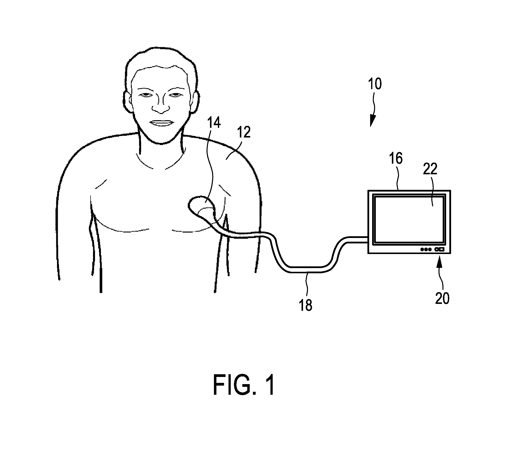
[0031]FIG. 1 illustrates a principle design of an ultrasound imaging system generally denoted by 10. This figure is used to explain the background of the ultrasound imaging. It shall be understood that the claimed ultrasound transducer assembly is not restricted to such kind of applications.

[0032]The ultrasound imaging system 10 is used for scanning an area or a volume of a body, e.g. of a patient 12. It shall be understood that the ultrasound system 10 may also be used for scanning other areas or volumes, e.g. body parts of animals or other living beings.

[0033]For scanning the patient, an ultrasound probe 14 is provided. In the embodiment shown in FIG. 1, the ultrasound probe 14 is connected to a console device 16. The console device 16 is shown as a mobile console. This console 16 may however also be realized as a stationary device. The console device 16 is connected to the probe 14 via an interface 18 formed as a via. Further, the console device 16 comprises an input device 20 to...


PUM


Abstract

An ultrasound transducer assembly (50), in particular for ultrasound imaging systems (10), is disclosed, comprising a transducer array (52) including a plurality of transducer elements (54) for emitting and receiving ultrasound waves (56). Each of the transducer elements (54) includes a first electrode (66) connected to a flexible membrane (64) and a second electrode (70). The assembly further comprises an integrated circuit device (60) connected to the transducer array (52) for driving the transducer elements (54), wherein the first electrodes (66) are electrically connected to each other and coupled to the integrated circuit device (60) for providing an alternating drive voltage to each of the transducer elements (54), wherein the second electrodes (70) are connected to a voltage supply for providing a bias voltage to the transducer elements (54), and wherein the first electrodes (66) are each connected by means of a via (76) to the integrated circuit device (60) and the vias (76) are fed through the second electrodes (70).

Description

FIELD OF THE INVENTION[0001]The present invention relates to an ultrasound transducer assembly, in particular for ultrasound imaging systems.BACKGROUND OF THE INVENTION[0002]In the field of ultrasound transducers and in particular in the field of ultrasound imaging systems, it is generally known to use micro-machined ultrasound transducer elements (CMUTs). Due to the fact that the capacitive micro-machined transducer elements can be fabricated by semiconductor processing techniques, the size of the transducers can be shrinked to very small feature sizes.[0003]Further, it is generally known to drive the ultrasound transducers including the micro-machined ultrasound transducer arrays by means of application specific integrated circuits, which serve as an electrical interface to each of the transducer elements.[0004]For integrating the whole transducer assembly, it is further known to fabricate the transducer array directly on a top surface of the application specific integrated circui...

Claims


Application Information

Patent Timeline
IPC IPC(8): A61B8/00B06B1/02
CPCA61B8/4483B06B1/0292A61B2562/12A61B8/467A61B8/461A61B8/4427
Inventor BROCK-FISHER, GEORGE ANTHONYSAVORD, BERNARD JOSEPH
Owner KONINKLJIJKE PHILIPS NV
Why Eureka
Try Eureka