Method and system for controlling a load

a technology of a load position and a control system, applied in the direction of load-engaging elements, transportation and packaging, etc., can solve the problems of increasing the inertia of spinning objects, the most common source of fatal accidents, and the man-hourly control of load orientation, etc., to reduce the speed of rotation and low potential impact on sideways torque

Active Publication Date: 2016-10-13
SAVANT TECH
View PDF1 Cites 23 Cited by
  • Summary
  • Abstract
  • Description
  • Claims
  • Application Information

AI Technical Summary

Benefits of technology

[0018]According to yet an embodiment, one or more battery(ies) is (are) arranged in the system for operation of the electrical motors therein, and where the electrical motors are adopted to charge the batteries when stopping the rotation of the flywheels. Using battery-operated motors, no electrical connection from the outside is necessary. Using the force used to stop the flywheels for charging the batteries, makes it possible to reduce the battery capacity and / or to make it possible to extend the period for operation between changing, substantially.
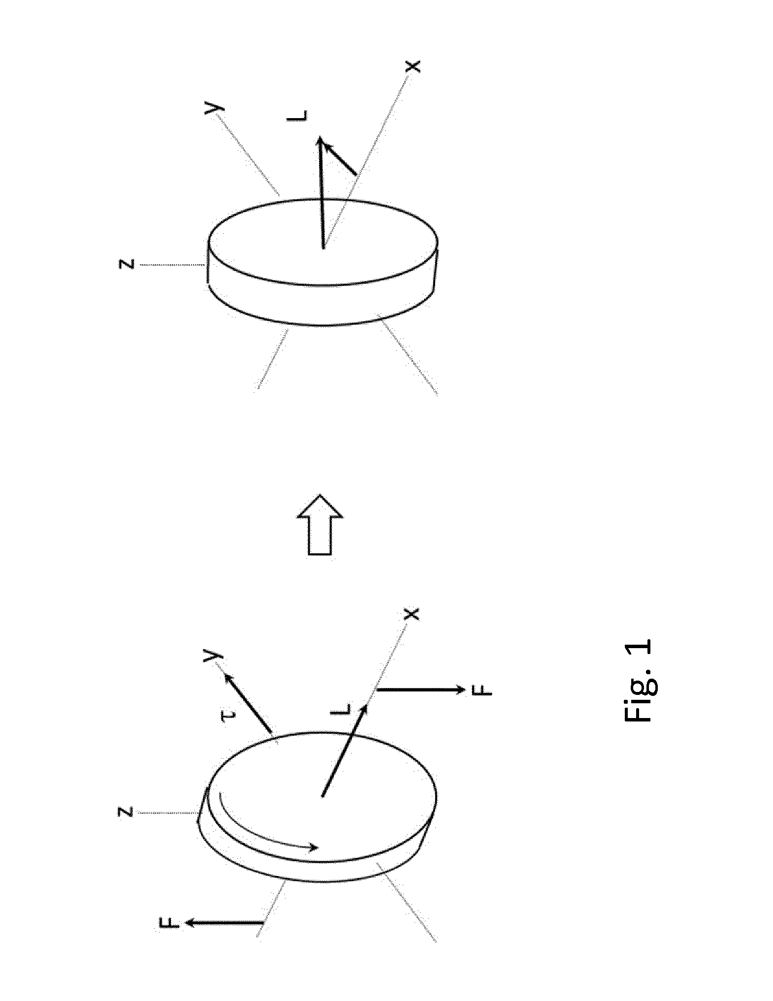
[0028]re-initialization of one or more of the flywheels, either by reducing the speed of rotation fully or partly, tilting the gimbals to a new starting position, and spinning up the flywheels again, or by stopping the flywheels and spinning up the flywheels in the opposite direction.
[0029]According to one embodiment, the flywheels are re-initiated by reducing the speed of rotation or stopping the rotation of the flywheels, tilting the flywheels to a new starting orientation, and restarting the rotation of the flywheels in positions of low potential impact on sideways torque.
[0030]According to another embodiment, the flywheels are re-initiated by stopping the rotation of the flywheels in positions of low potential impact on sideways torque and restart the rotation in the opposite direction.

Problems solved by technology

Manual handling / control of the orientation of loads may represent a significant hazard, especially if the load is heavy and / or have large dimensions along one or more axes.
According to the Petroleum Safety Authority Norway, work involving cranes and the associated handling of the loads is the most common source of fatal accidents in the offshore industry.
The system allows for stabilization of a suspended load but not for controlling the position and movement of a load.
Increasing the inertia of the spinning objects has its obvious limitations in the space available for this purpose, as have the total weight of the spinning objects, and the obtainable speed of rotation.
Disconnecting the load from the flywheel by the use of clutches for repositioning the flywheel has the negative effect of losing control of the load and its rotation for the time the load is disconnected.

Method used


Image

  • Method and system for controlling a load
  • Method and system for controlling a load
  • Method and system for controlling a load

Examples


Embodiment Construction

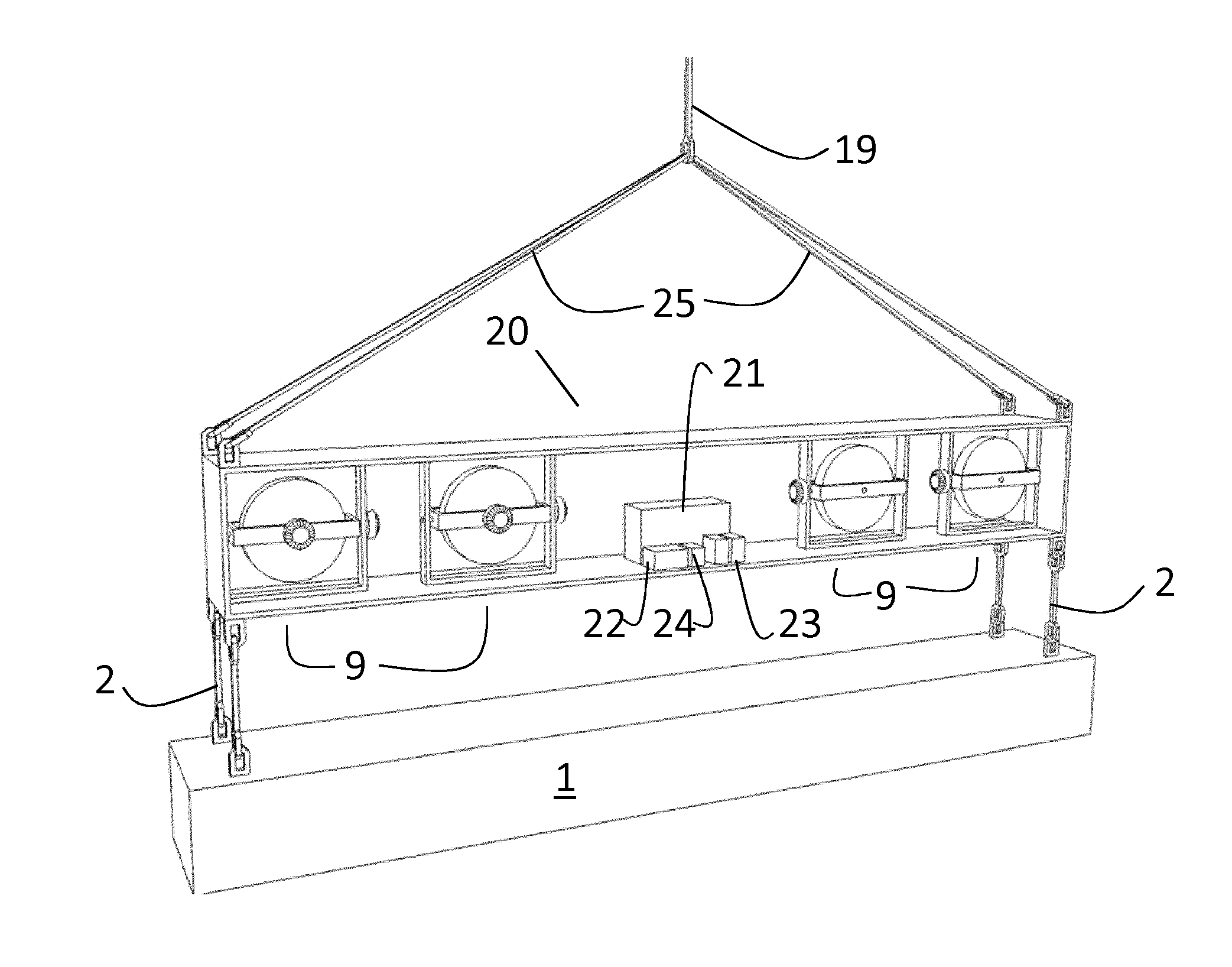
[0044]FIG. 3 illustrates a flywheel unit 9, comprising a flywheel 10 arranged in a gimbal 11. The rotation of the flywheel is controlled by means of an electrical motor 12, connected to a control system via not shown cables. The flywheel is rotatable about an axis of rotation 8. In the illustrated embodiment, the electrical motor and the flywheel has a common axis of rotation 8. The skilled person will understand that a gear or the like may be arranged between the electrical motor 12 and a flywheel shaft 7, without leaving the scope of the invention. The skilled person will also understand that the term “flywheel” is to be understood as any convenient spinning object being balanced about an axis of rotation.

[0045]The gimbal 11 is again rotary arranged in a gimbal frame 15. The gimbal 11 is rotary arranged about a gimbal frame axis of rotation 6 being substantially perpendicular to the axis of rotation for the flywheel preferably in or close to the centre of gravity of the flywheel.

[...


PUM


Abstract

A system for controlling the orientation of a hanging load, the system comprising a lifting frame (20) being connectable to a load to be lifted, on which lifting frame two or more flywheel units (9) are arranged, the flywheel units (9) each comprising a flywheel (10) rotary arranged in a gimbal (11) which again is rotary arranged in a gimbal support (15) along an axis of rotation (6) being perpendicular to the axis of rotation (8) of the flywheel (10), where an electric motor (12) is arranged for rotating the flywheel (10), and a tilting motor (13) is arranged to tilt the gimbal by rotating the gimbal about its axis of rotation (6), wherein the system further comprises a control unit for individually controlling the speed and the direction of rotation of the flywheels, and the tilting of the gimbals, the control system being adopted for re-initialization of a flywheel units (9) either by reducing the speed of rotation fully or partly, tilting the gimbals to a new starting position, and spinning up the flywheels again; or by stopping the flywheels and spinning up the flywheels in the opposite direction.

Description

TECHNICAL FIELD[0001]The present invention relates to a method and a system for controlling the position and movement of a load. More specifically, the present invention relates to a system and method for controlling the rotational movement of a load suspended in a lifting cable.BACKGROUND ART[0002]Control of rotation and accurate positioning of loads are important in handling loads by means of cranes. When using a single lifting cable the crane operator may control the load, or the centre of gravity of the load, in three dimensions, but not in a fourth dimension, the orientation of the load in the horizontal plane. To control and adjust the orientation of the load, manual adjustments or adjustments using auxiliary lines / wires has to be used. Manual handling / control of the orientation of loads may represent a significant hazard, especially if the load is heavy and / or have large dimensions along one or more axes. According to the Petroleum Safety Authority Norway, work involving cra...

Claims


Application Information

Patent Timeline
Patent Type & Authority Applications(United States)
IPC IPC(8): B66C13/08
CPCB66C13/085B66C1/10B66C13/22B66C13/40
Inventor BANG, KNUT E.
Owner SAVANT TECH
Why Eureka
Try Eureka