

Battery-packaging material
Active Publication Date: 2016-10-13
DAI NIPPON PRINTING CO LTD
View PDF2 Cites 9 Cited by
- Summary
- Abstract
- Description
- Claims
- Application Information
AI Technical Summary
Benefits of technology
The present invention relates to a battery packaging material that can be easily molded into desired shapes without generating pinholes or cracks. The material has a metal layer made of aluminum foil, which can follow the shape of the mold during molding. Additionally, the material has a base material layer made of a biaxially stretched film that includes a polyester resin layer and a polyamide resin layer. The base material layer has excellent resistance to electrolytic solution and can effectively prevent the dissolution or damage of the material when exposed to such solutions. These features make the battery packaging material ideal for improving production efficiency and ensuring battery safety.
Problems solved by technology
However, metallic battery packaging materials that have been often used heretofore have the disadvantage that it is difficult to keep up with diversification of shapes, and there is a limit to weight reduction.
However, such a film-shaped packaging material is thinner as compared to a metallic packaging material, and has the disadvantage that pinholes and cracks are easily generated during molding.
If pinholes and cracks are generated in a battery packaging material, an electrolytic solution may permeate to a metal layer to form a metal precipitate, resulting in occurrence of a short-circuit, and therefore it is absolutely necessary that a film-shaped battery packaging material have a property that makes it hard to generate pinholes during molding, i.e. excellent moldability.
However, a polyester film is inferior in moldability to a polyamide film etc., and the use of a polyester film as a base material layer causes the problem that pinholes are easily generated during molding.
Therefore, when a polyester film is used as a base material layer for improving electrolytic solution resistance, it is particularly difficult to improve the moldability of a battery packaging material.
However, there is the problem that if an electrolytic solution is deposited on a base material surface in production of a battery using a battery packaging material including a nylon film as a base material, the base material surface is whitened or melted.
However, a polyester film is poor in moldability, and therefore has the problem that pinholes are easily generated during molding.
Method used
View moreImage
Smart ImageViewing Examples

Examples
examples
[0113]The first aspect and the second aspect of the present invention will be described in detail below by showing examples and comparative examples. It is to be noted that the present invention is not limited to examples.
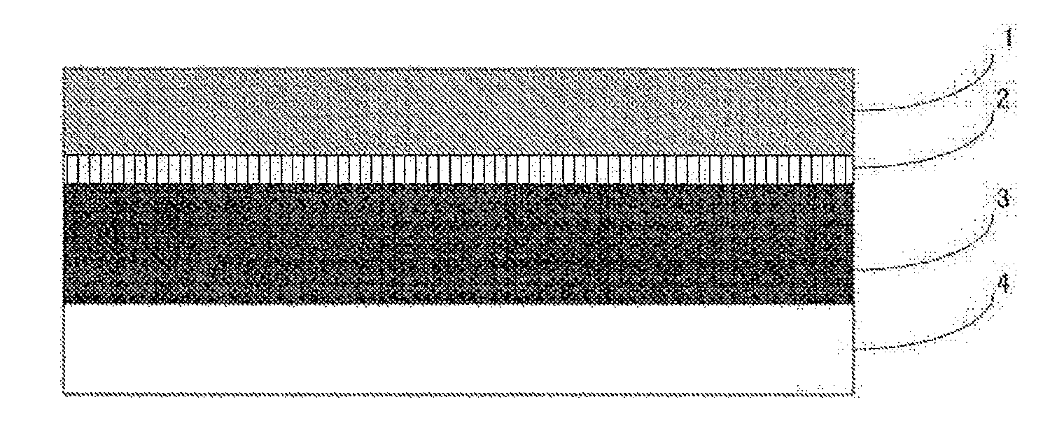
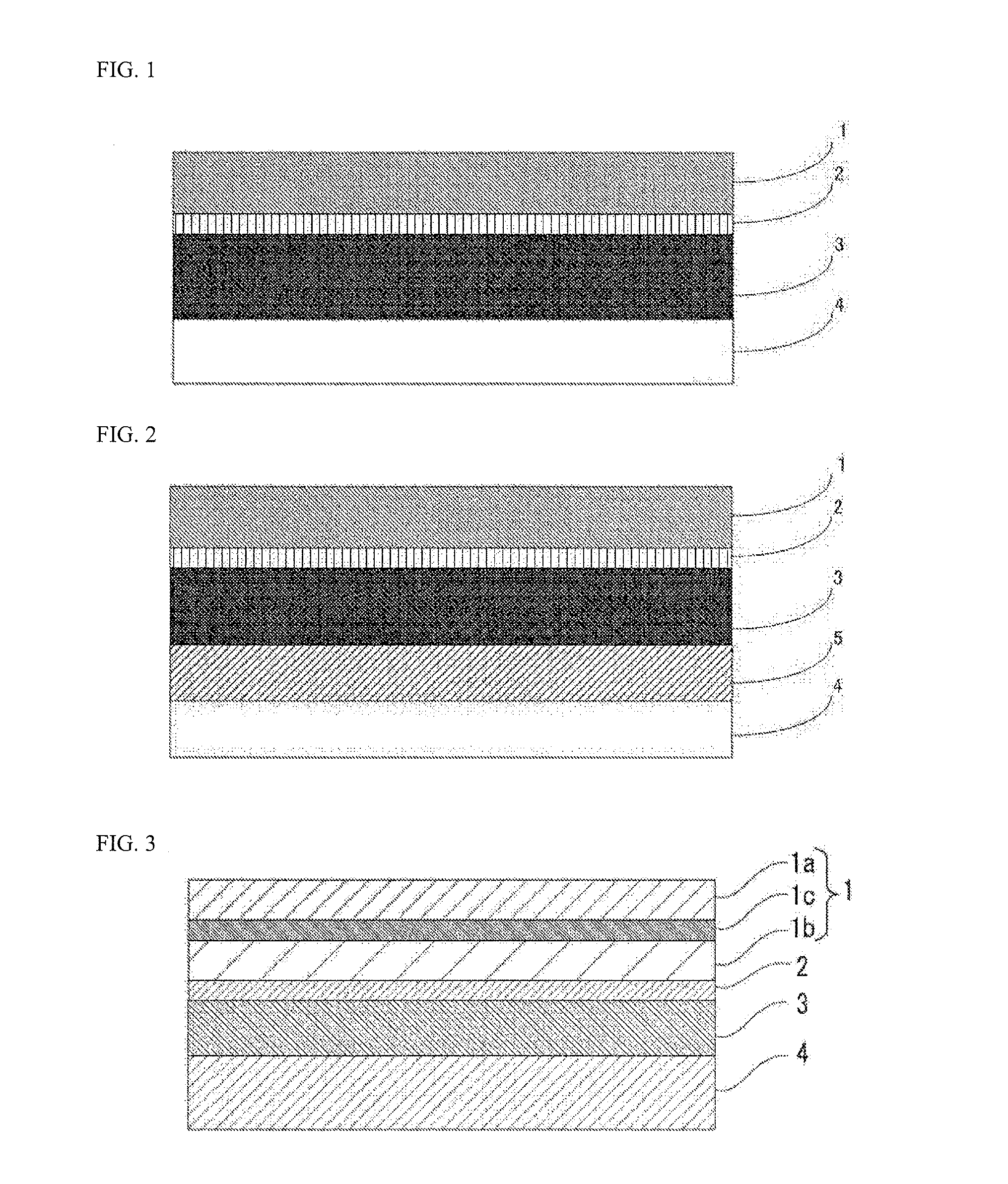
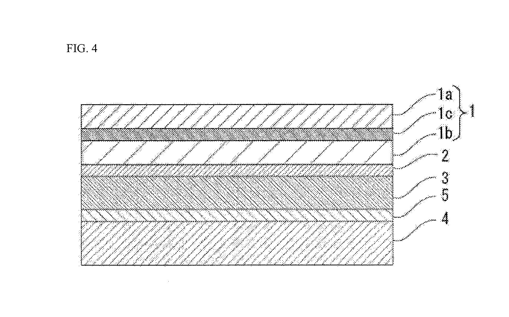
[0114]A battery packaging material including a laminate with a base material layer 1, an adhesive layer 2, a metal layer 3, an adhesive layer 5 and a sealant layer 4 laminated in this order was produced by laminating the adhesive layer 5 and the sealant layer 4 by a thermal lamination method to a laminate with the base material layer 1, the adhesive layer 2 and the metal layer 3 laminated in this order. Details of conditions for producing the battery packaging material are as shown below.
Login to View More PUM
| Property | Measurement | Unit |
|---|---|---|
| Fraction | aaaaa | aaaaa |
| Fraction | aaaaa | aaaaa |
| Thickness | aaaaa | aaaaa |
Abstract
To provide a technique for a battery-packaging material made of a film-form laminate in which at least a base material layer, an adhesive layer, a metal layer, and a sealant layer are laminated successively, wherein: electrolytic solution resistance is further improved by including a polyester film in the base material layer; cracks and pinholes are less likely to be created at the time of forming the polyester-film-including base material layer; and formability is improved. This battery-packaging material is made of a laminate in which at least a base material layer, an adhesive layer, a metal layer, and a sealant layer are laminated successively, wherein: the base material layer includes a polyester film; and the metal layer is an aluminum foil in which the 0.2% proof stress at the time of performing a tensile test in a direction parallel to the rolling direction is from 55 to 140 N / mm2.
Description
TECHNICAL FIELD[0001]The present invention relates to a battery packaging material which has excellent moldability with pinholes and cracks hardly generated during molding and which has excellent electrolytic solution resistance.BACKGROUND ART[0002]Various types of batteries have been developed heretofore, and in every battery, a packaging material is an essential member for sealing battery elements such as an electrode and an electrolyte. Metallic packaging materials have been often used heretofore as battery packagings.[0003]On the other hand, in recent years, batteries have been required to be diversified in shape and to be thinned and lightened with improvement of performance of electric cars, hybrid electric cars, personal computers, cameras, mobile phones and so on. However, metallic battery packaging materials that have been often used heretofore have the disadvantage that it is difficult to keep up with diversification of shapes, and there is a limit to weight reduction.[000...
Claims
Login to View More Application Information
Patent Timeline
 IPC IPC(8): H01M2/02B32B7/12B32B15/088B32B15/20B32B27/08B32B27/34B32B27/36H01M10/0525B32B15/09H01M50/119H01M50/121H01M50/129H01M50/133H01M50/141H01M50/145
CPCH01M2/0287H01M2220/30H01M2/0262H01M10/0525B32B7/12B32B15/088B32B15/09B32B27/08B32B27/34B32B27/36B32B15/20B32B2255/06B32B2307/54B32B2457/10H01M2220/20H01M2/026B32B7/04B32B2255/10B32B2255/26B32B2307/202B32B2307/31B32B2307/518B32B2307/732Y02E60/10H01M50/124H01M50/1245Y02P70/50H01M50/145H01M50/141H01M50/133H01M50/121H01M50/129H01M50/119H01M10/052H01M50/14
Inventor TAKAHAGI, ATSUKOAKITA, HIROHISANISHIDA, SUMITOYAMASHITA, RIKIYA
Owner DAI NIPPON PRINTING CO LTD