

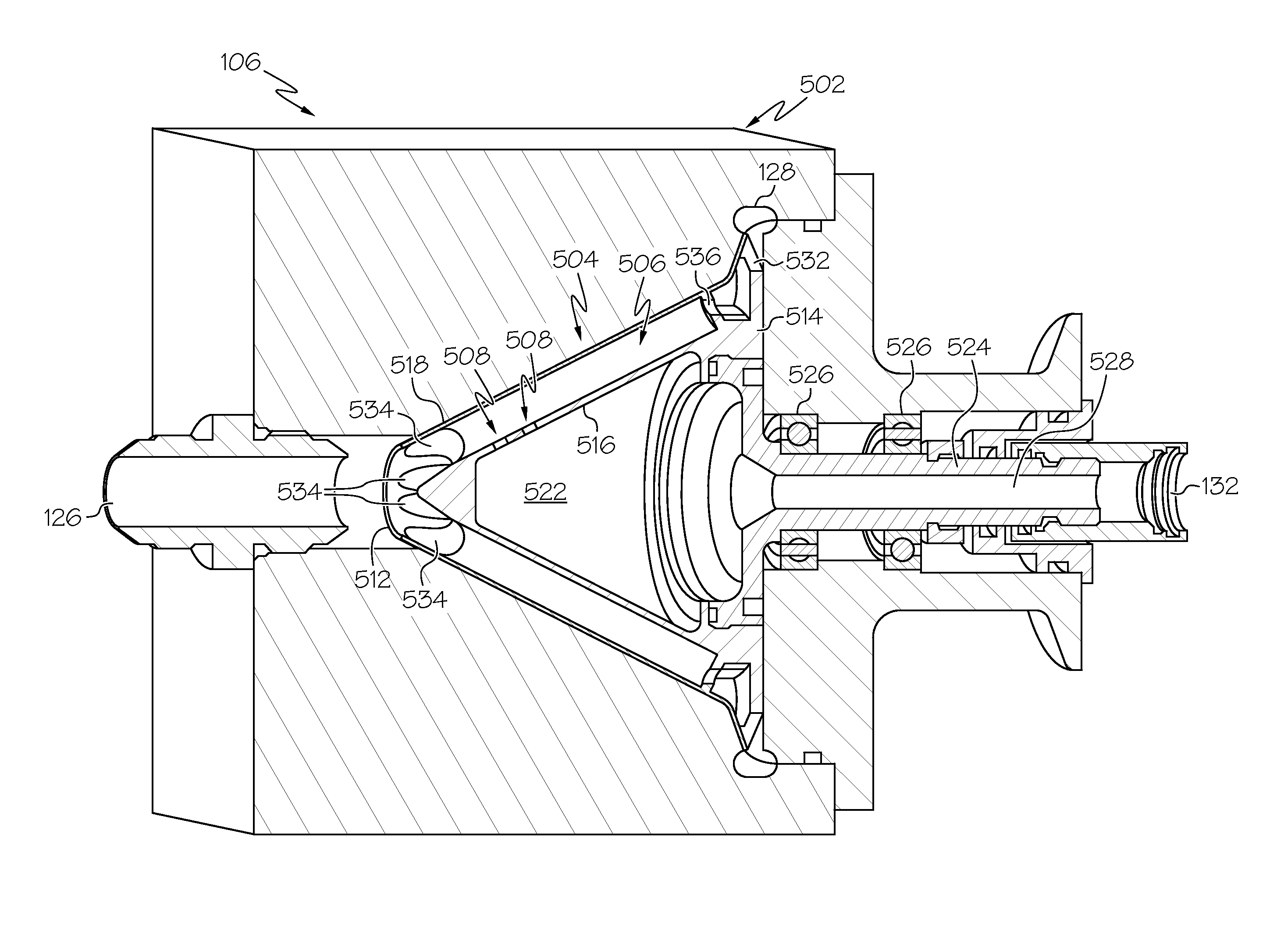
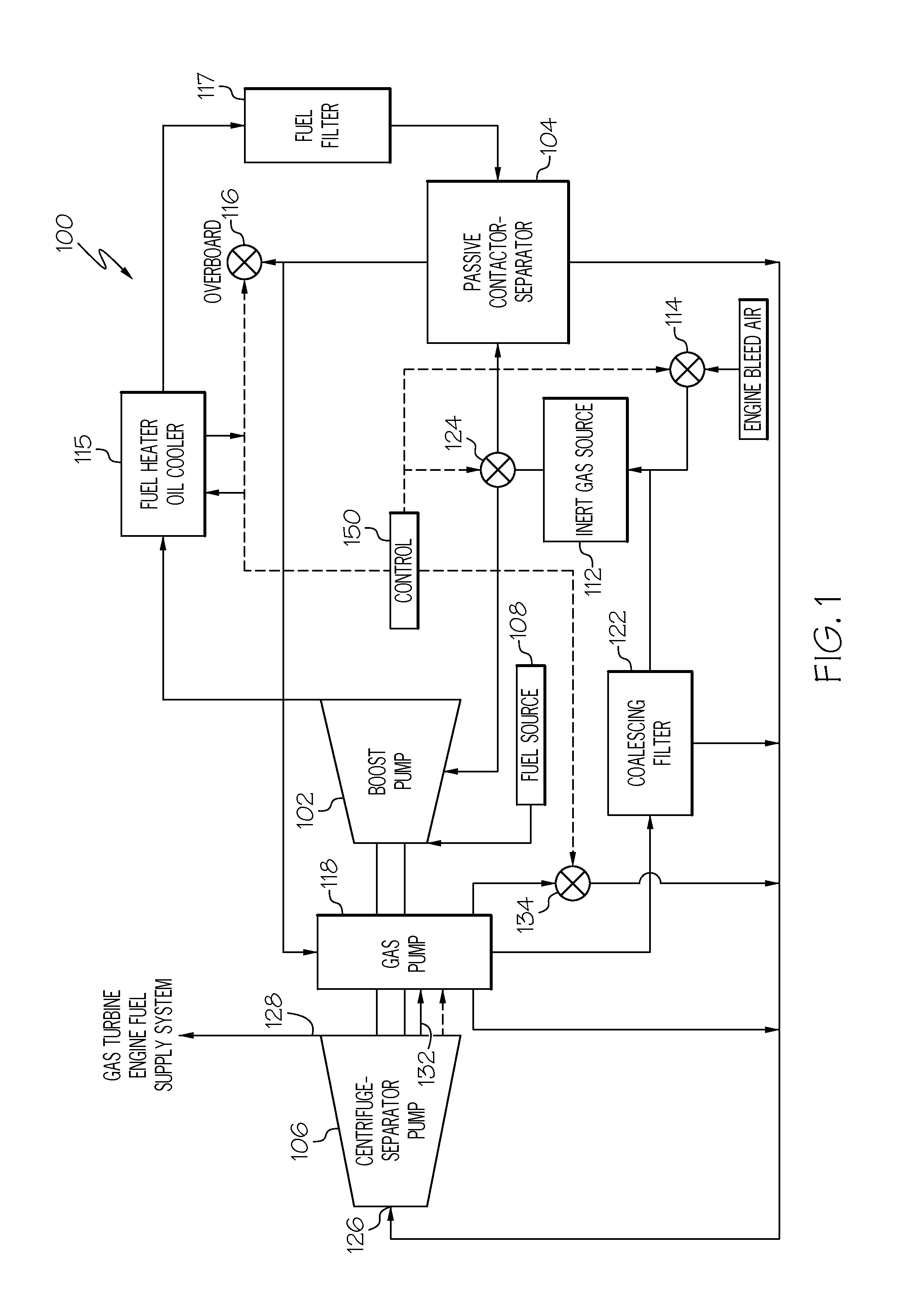
In-line continuous flow liquid-gas separator-pump
a liquid gas separator and continuous flow technology, applied in the direction of liquid degasification, separation process, centrifuge, etc., can solve the problems of reducing the efficiency of the fuel system, limiting the ability of the fuel to absorb heat beyond, thermal degradation, etc., to prevent the fuel pressure from dropping too low, improve the transition of fuel flow, and quickly and efficiently degas a liquid
- Summary
- Abstract
- Description
- Claims
- Application Information
AI Technical Summary
Benefits of technology
Problems solved by technology
Method used
Image

Examples
Embodiment Construction
[0015]The following detailed description is merely exemplary in nature and is not intended to limit the invention or the application and uses of the invention. As used herein, the word “exemplary” means “serving as an example, instance, or illustration.” Thus, any embodiment described herein as “exemplary” is not necessarily to be construed as preferred or advantageous over other embodiments. All of the embodiments described herein are exemplary embodiments provided to enable persons skilled in the art to make or use the invention and not to limit the scope of the invention which is defined by the claims. Furthermore, there is no intention to be bound by any expressed or implied theory presented in the preceding technical field, background, brief summary, or the following detailed description.
[0016]With the above in mind, it will be appreciated that although embodiments of an in-line continuous flow liquid-gas separator-pump are described herein in the context of an aircraft fuel de...
PUM
| Property | Measurement | Unit |
|---|---|---|
| temperature | aaaaa | aaaaa |
| drive torque | aaaaa | aaaaa |
| diameter | aaaaa | aaaaa |
Abstract
Description
Claims
Application Information