
Low heat loss cryogenic liquid container

Inactive Publication Date: 2016-10-20
KOREA INST OF SCI & TECH
View PDF3 Cites 2 Cited by
  • Summary
  • Abstract
  • Description
  • Claims
  • Application Information

AI Technical Summary

Benefits of technology

The present invention is related to a low heat loss cryogenic liquid container. The technical effects of the invention include: providing a support capable of supporting an inner container between an inner lower surface of an outer container and an outer lower surface of the inner container to minimize conduction heat intrusion with the improvement in structural stability; and providing a support capable of absorbing displacement and deformation of the inner container depending on heat contraction and expansion. These effects are achieved through the use of a low heat conductivity material, such as a strut member and heat isolation blocks, in the support structure and at least one spring coupled to the strut member to absorb displacement and deformation of the inner container. The invention reduces heat conduction and relieves thermal stress on the inner container, resulting in improved efficiency and stability of the cryogenic liquid container.

Problems solved by technology

For the above, various methods such as vacuum insulation, multilayer insulation (MLI), and the like have been complexly utilized in the cryogenic equipment.
Thus, there is a problem in that the support serves as a conduction heat transfer path from the outside to the cryogenic liquid.
Since the difference in temperature between both ends is large (approximately 280K), conductive heat transfer through the support may be extremely large.
Therefore, when heat intrusion resulting from the conduction heat transfer is not effectively reduced, a rate of loss of evaporation of the cryogenic liquid sharply increases due to a large quantity of heat inflow, which leads to a problem that a liquid desired to be stored cannot be stored for a long time.
Further, such a cryogenic container has a disadvantage in that the inner container is supported inside the outer container in a suspended state only, and thus structural stability is relatively low.

Method used


Image

  • Low heat loss cryogenic liquid container
  • Low heat loss cryogenic liquid container
  • Low heat loss cryogenic liquid container

Examples


Embodiment Construction

[0029]Hereinafter, a low heat loss cryogenic liquid container according to the present invention will be described in detail with reference to the accompanying drawings.

[0030]The low heat loss cryogenic liquid container illustrated in the drawings in accordance with the present invention will be described as being applied to a cryogenic liquid storage system, but it may be applied to a liquefaction system.

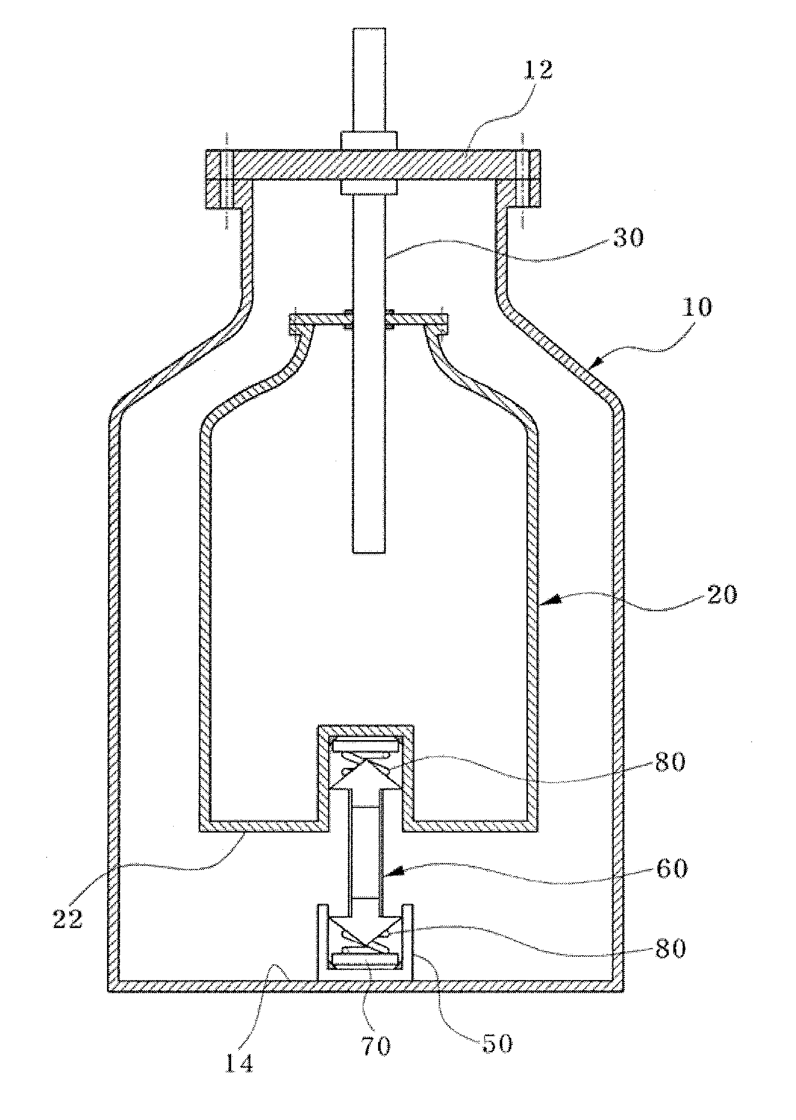
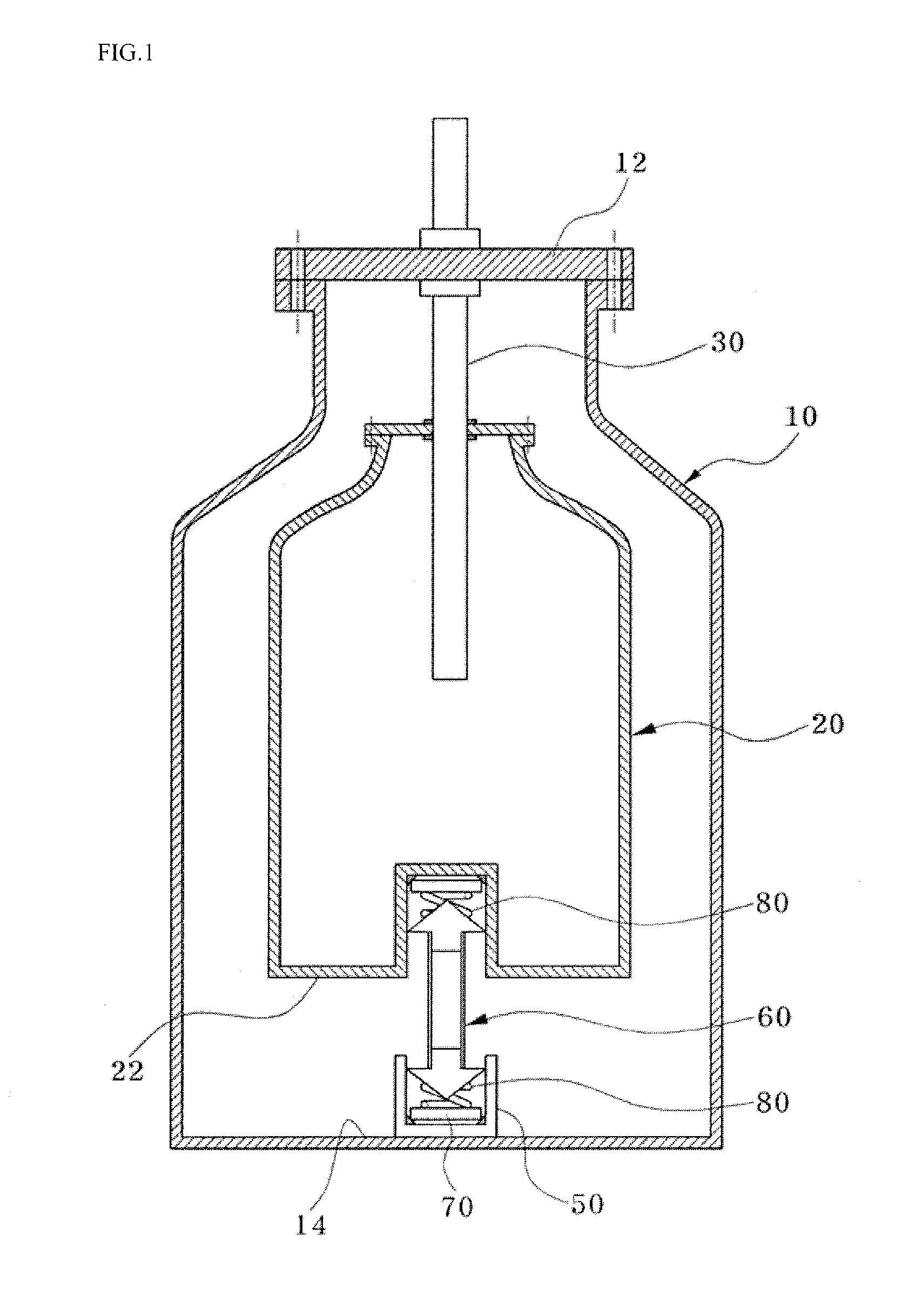
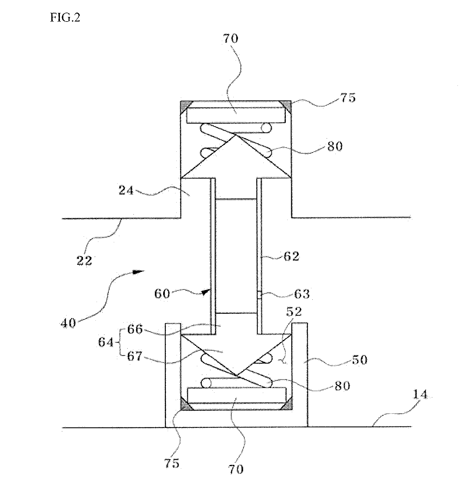
[0031]FIG. 1 is a schematic sectional view illustrating a low heat loss cryogenic liquid container according to the present invention, and FIG. 2 is a partially enlarged view illustrating the low heat loss cryogenic liquid container according to the present invention.

[0032]Referring to FIGS. 1 and 2, the low heat loss cryogenic liquid container according to the present invention includes an outer container 10, an inner container 20, a liquid inflow / outflow pipe 30, and a support 40.

[0033]The outer container 10 is a tub-like container, to an upper end of which an upper end cover 12 ...


PUM


Abstract

Provided is a low heat loss cryogenic liquid container, which includes: an outer container, to an upper end of which an upper end cover is coupled and an interior of which is maintained in a vacuum; an inner container that is disposed inside the outer container apart from an inner wall of the outer container and contains a cryogenic liquid; a liquid inflow / outflow pipe that connects an exterior of the outer container and an interior of the inner container and serves as a passage for charging and / or discharging the cryogenic liquid; and a support including a strut member that is disposed between an inner lower surface of the outer container and an outer lower surface of the inner container and is formed of a low heat conductivity material to interrupt heat conduction, and springs disposed at least one position between an upper end of the strut member and the outer lower surface of the inner container, between a lower end of the strut member and the inner lower surface of the outer container, and between both of the ends of the strut member.

Description

CROSS-REFERENCE TO RELATED APPLICATION[0001]This application claims the benefit of Korean Patent Application No. 2015-0053295, filed on Apr. 15, 2015, the disclosure of which is hereby incorporated herein by reference in its entirety.BACKGROUND OF THE INVENTION[0002]1. Field of the Invention[0003]The present invention relates generally to a low heat loss cryogenic liquid container, and more particularly, to a low heat loss cryogenic liquid container used in a storage system for storing a cryogenic liquid such as liquefied natural gas (LNG), liquefied petroleum gas (LPG), liquid oxygen, liquid nitrogen, liquid helium, or liquid hydrogen and a liquefaction system for liquefying the gases.[0004]2. Description of the Related Art[0005]Recently, as the measure for solving problems of air pollution and global warming caused by excessive use of fossil fuel, researches for a system using energy sources other than hydrocarbon fuel have been actively carried out in domestic and foreign countri...

Claims


Application Information

Patent Timeline
IPC IPC(8): F17C13/00F17C3/08
CPCF17C13/001F17C3/08F17C2203/0304F17C2203/0629F17C2270/01F17C2205/0149F17C2205/0352F17C2221/033F17C2260/031F17C2203/0391F17C2201/032F17C2201/056F17C2203/014F17C2221/011F17C2221/012F17C2221/014F17C2221/017F17C2221/035F17C2223/0153F17C2223/0161F17C2223/033F17C2260/033Y02E60/32
Inventor KARNG, SARNG WOOKIM, SEO YOUNGBAIK, JONG HOONOH, IN HWAN
Owner KOREA INST OF SCI & TECH
Features
  • Generate Ideas
  • Intellectual Property
  • Life Sciences
  • Materials
  • Tech Scout
  • Unparalleled Data Quality
  • Higher Quality Content
  • 60% Fewer Hallucinations
Learn More