Fuel filling system and fuel filling method thereof

a fuel tank and fuel technology, applied in the direction of electrochemical generators, container filling under pressure, discharging methods, etc., can solve the problems of large measurement error in the prediction temperature serving as the standard, difficult to accurately determine the validity of information sent from the vehicle side, and difficult to accurately calculate the predicted temperature. , to achieve the effect of preventing the temperature of the fuel tank from rising, reducing misjudgment, and improving the determination accuracy

Active Publication Date: 2016-10-20
HONDA MOTOR CO LTD
View PDF9 Cites 22 Cited by
  • Summary
  • Abstract
  • Description
  • Claims
  • Application Information

AI Technical Summary

Benefits of technology

[0010]The present invention has an object of providing a fuel filling system and a fuel filling method thereof that can determine the validity of information sent from the vehicle while filling fuel with high accuracy.
[0031]According to the tenth aspect of the present invention, the validity of information sent from the vehicle side can be accurately determined for the same reasons as the aforementioned first aspect of the invention. In addition, according to the present invention, since it will not mistakenly change to an inappropriate filling control law during the filling of fuel due to decreasing the misjudgment compared to conventionally, it is possible to shorten the time required until refilling the fuel tank.

Problems solved by technology

However, the temperature of fuel in the hydrogen tank during filling actually varies according to the heat released from the surfaces of the hydrogen tank, and thus it is difficult to accurately calculate the predicted temperature.
For this reason, with the method of Patent Document 1, the measurement error in the predicted temperature serving as the standard is great, and it is difficult to accurately determine the validity of information sent from the vehicle side.

Method used


Image

  • Fuel filling system and fuel filling method thereof
  • Fuel filling system and fuel filling method thereof
  • Fuel filling system and fuel filling method thereof

Examples


Embodiment Construction

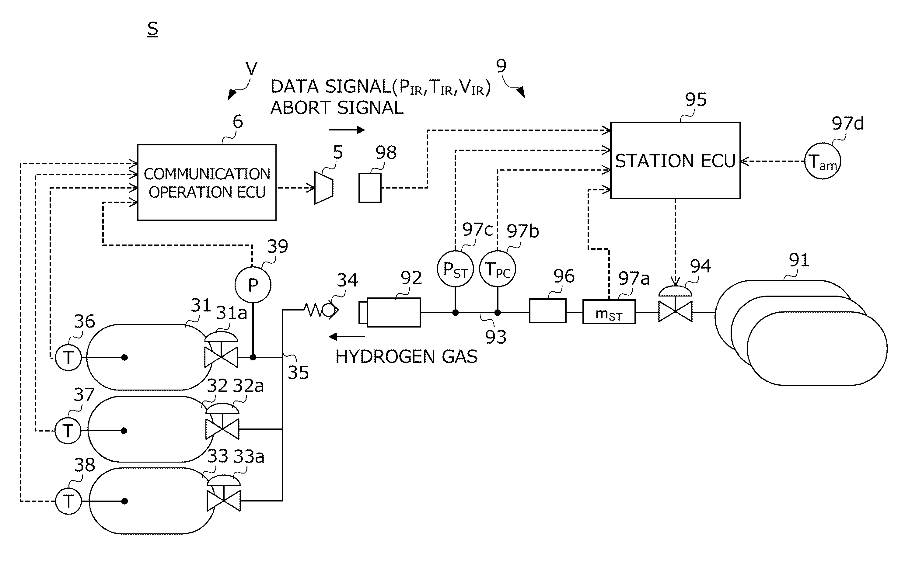
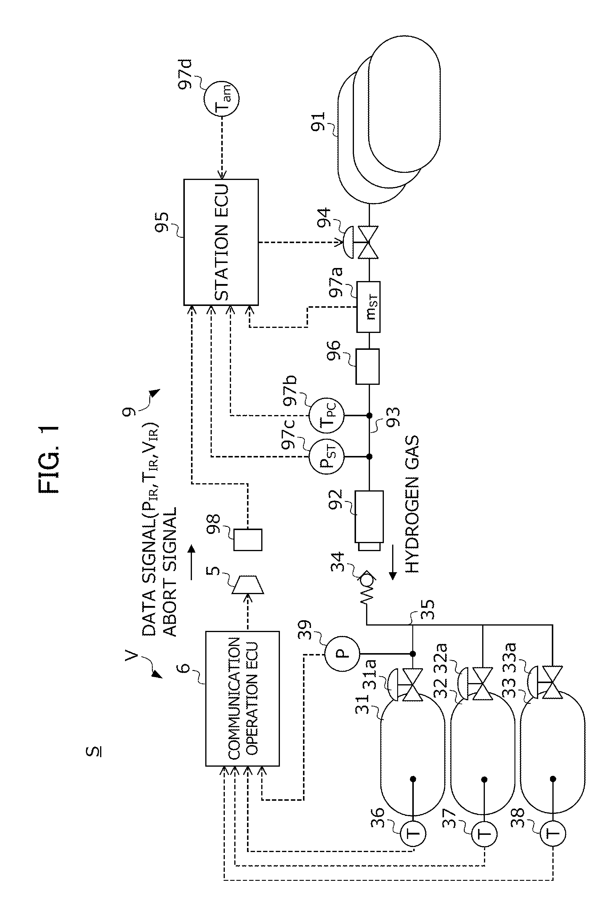
[0038]An embodiment of the present invention will be explained hereinafter while referencing the drawings. FIG. 1 is a view showing the configuration of a hydrogen filling system S to which the fuel filling method according to the present embodiment is applied. The hydrogen filling system S is configured by combining a fuel cell vehicle V that travels with hydrogen gas as the fluid fuel, and a hydrogen station 9 serving as an external filling device that supplies hydrogen gas to a hydrogen tank 31 of this vehicle V. Hereinafter, first the configuration on the vehicle V side will be explained, and then the configuration on the hydrogen station 9 side will be explained.

[0039]The fuel cell vehicle V includes a hydrogen tank system 3 that stores hydrogen gas supplied from the hydrogen station 9, a communication operation ECU 6 that generates data signals including information related to the hydrogen tank system 3, and an infrared transmitter 5 that sends the data signals generated by th...


PUM


Abstract

The present invention provides a fuel filling system and a fuel filling method thereof that can determine the validity of information transmitted from a vehicle side while filling fuel with high accuracy. A hydrogen gas filling method of a hydrogen filling system includes: a step of filling hydrogen gas from a hydrogen station to a hydrogen tank under a predetermined filling control law (S2); and a determination step of determining whether a measurement error parameter corresponding to a difference between a filling amount of hydrogen gas calculated using information transmitted from the vehicle side and a filling amount of hydrogen gas calculated using a mass flow meter is within a predetermined permissible range (S9). In the filling step, the filling control law is changed after starting the filling of hydrogen gas, according to a determination result obtained in the determination step (S13 and S16).

Description

[0001]This application is based on and claims the benefit of priority from Japanese Patent Application No. 2015-082701, filed on 14 Apr. 2015, the content of which is incorporated herein by reference.BACKGROUND OF THE INVENTION[0002]1. Field of the Invention[0003]The present invention relates to a fuel filling system and a fuel filling method thereof.[0004]2. Related Art[0005]Fuel cell vehicles travel by supplying oxygenated air and hydrogen to the fuel cell, and driving an electric motor using the electric power thereby generated. In recent years, progress has been made in the practical implementation of fuel cell vehicles employing such fuel cells as the energy source for generating motive power. Although hydrogen is required to generate electric power by fuel cells, with the fuel cell vehicles of recent years, vehicles have become mainstream that store a sufficient amount of hydrogen in advance in a high-pressure tank or a hydrogen tank equipped with a storage alloy, and use the ...

Claims


Application Information

Patent Timeline
Patent Type & Authority Applications(United States)
IPC IPC(8): F17C13/02F17C5/06
CPCF17C13/02F17C2270/0184F17C13/025F17C13/023F17C13/026F17C13/028F17C2221/012F17C2250/0621F17C2250/0631F17C2250/0434F17C2250/0439F17C2250/0491F17C2250/0694F17C2250/0421F17C2260/022F17C2260/025F17C2265/065F17C5/06F17C2205/0142F17C2205/0146F17C2223/0123F17C2223/036F17C2225/0123F17C2225/036F17C2227/0337F17C2227/047F17C2250/032F17C2250/043F17C2250/0443Y02E60/32
Inventor HANDA, KIYOSHI
Owner HONDA MOTOR CO LTD
Why Eureka
Try Eureka