
Bearing Monitoring Apparatus and Method

Active Publication Date: 2016-10-20
AB SKF
View PDF1 Cites 10 Cited by
  • Summary
  • Abstract
  • Description
  • Claims
  • Application Information

AI Technical Summary

Benefits of technology

This patent describes a bearing monitoring system that uses strain signals to detect damage or imprecise movement in bearings. The system uses fiber optic technologies to transmit data, which can be collected and processed using a data processing unit. The system can detect both bearing speed and load and adjust the thresholds for detecting defects accordingly, which improves accuracy. The system is particularly useful in applications where sensitive components are located at deep sea levels, where fiber optic technology is more robust. The technology also provides an easier way to interpret the signals and take appropriate action to prevent damage or downtime.

Problems solved by technology

However, this technology is not available for some important fields of application.
Commonly used condition monitoring systems are difficult to deploy in subsea conditions due to the electronic packaging requirements and the high data bandwidth.
Besides that, electronic transmission over long distances, for example when running alongside power lines, is sensitive to electromagnetic interference.
Monitoring of the asset is problematic as the electronics can be less reliable than the mechanical system being monitored by the electronics.
Therefore, for the purpose of bearing monitoring, conventional acceleration measurement is prohibited in these applications.
Fibre optic accelerometers that have been investigated are however not capable of delivering the required resolution for monitoring the condition of the bearing.

Method used


Image

  • Bearing Monitoring Apparatus and Method
  • Bearing Monitoring Apparatus and Method
  • Bearing Monitoring Apparatus and Method

Examples


Embodiment Construction

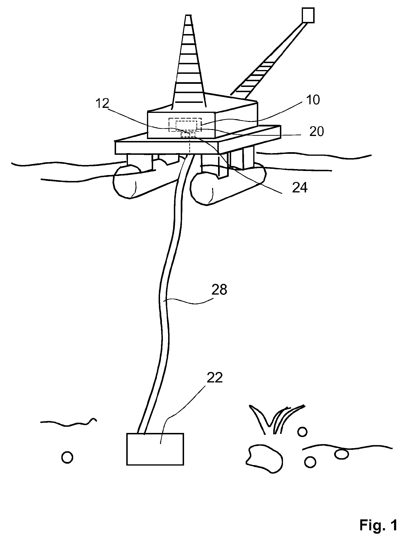
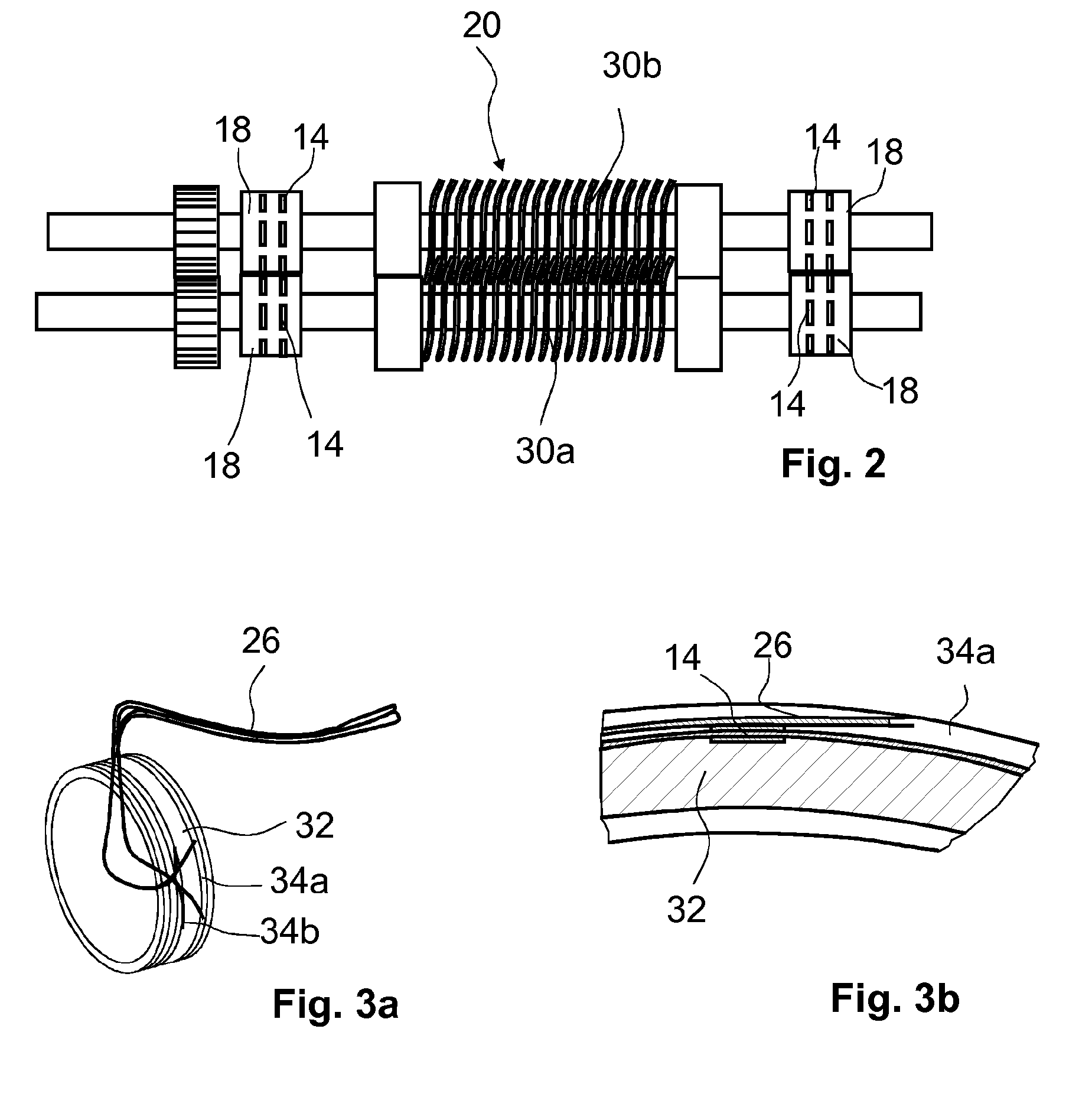
[0036]FIG. 1 illustrates a system including a deep sea pump 22 with bearings 18 (FIG. 2) equipped with multiple sensors including strain sensors 14 and a bearing monitoring apparatus 10 located in a floating oil rig at sea level. The sensor signals are transmitted from the deep sea pump 22 to the bearing monitoring apparatus 10 by means of optical fibers 26 in a so-called umbilical 28 connecting the sea-level part of the system with the deep sea unit.

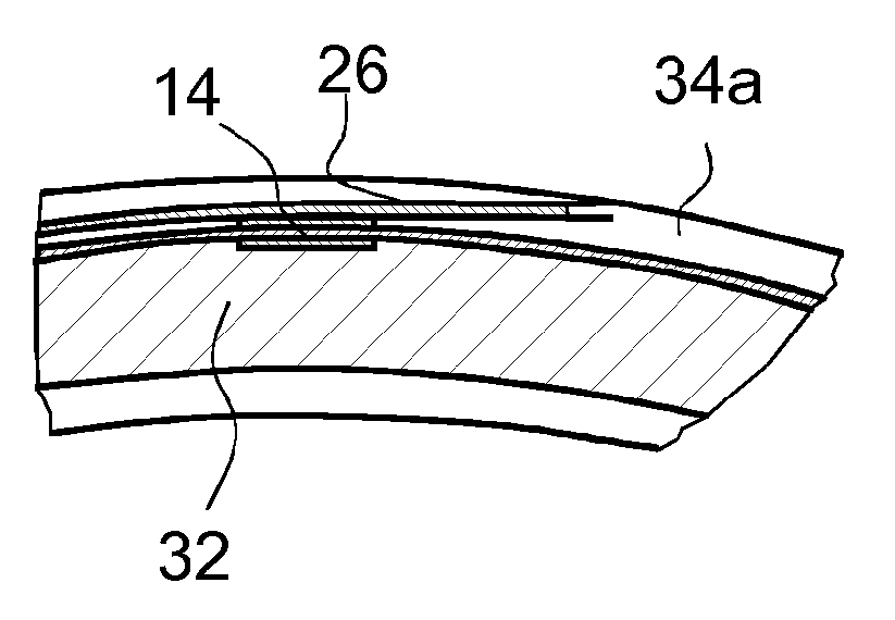
[0037]At the sea-level side, the fibers 26 are connected to a data acquisition unit 24 forming the core part of the interface 12. Optoelectronic units are provided in the data acquisition unit 24 that illuminate the sensor network and record the optical reflection (wavelength change) from each discrete sensor 14 and output them as strains and temperatures.

[0038]Stainless-steel tubes protect the fibers inside the pump 22. In the actual application, the optical fibers 26 are guided together with power supply lines and many control signals...


PUM


Abstract

A bearing monitoring apparatus including at least one interface for receiving strain signals detected by at least one strain sensor mounted on a bearing and at least one data processing unit configured to monitor the bearing by detecting bearing defects based on the strain signals is provided. The data processing unit is configured to subject the strain signal to a high pass filtering. A limit frequency of the high pass filter is set higher than a typical ball pass frequency of the bearing to be monitored, to calculate a quantity representative of the amplitude of the envelope signal of the high-pass filtered strain signal, to compare the peak hold of the envelope signal with an envelope threshold value, to classify the bearing using the result of the envelope comparison and to issue at least one warning signal if the bearing is classified as defective.

Description

FIELD OF THE INVENTION[0001]The Invention relates to a bearing monitoring apparatus and to a bearing monitoring method employing strain signals.BACKGROUND OF THE INVENTION[0002]Bearing monitoring technology using vibration signals obtained by accelerometers is well known and mature technology. However, this technology is not available for some important fields of application.[0003]One important example is subsea devices such as deep sea pumps. Commonly used condition monitoring systems are difficult to deploy in subsea conditions due to the electronic packaging requirements and the high data bandwidth. Besides that, electronic transmission over long distances, for example when running alongside power lines, is sensitive to electromagnetic interference.[0004]Deep sea pumps used for oil and gas applications are important assets for the production of an oil rig. Monitoring of the asset is problematic as the electronics can be less reliable than the mechanical system being monitored by ...

Claims


Application Information

Patent Timeline
IPC IPC(8): G01M13/04F16C19/52F16C41/00G01L1/24
CPCG01M13/04F16C41/008F16C19/522G01L1/246G01M13/045F16C33/586
Inventor VAN DER HAM, ANDREAS CLEMENSDEN, NICOLAAS SIMON WILLEMREEDMAN, ADAM V.C.
Owner AB SKF
Learn More