System and Method for a Capacitive Sensor

Active Publication Date: 2016-10-20
INFINEON TECH AG
View PDF5 Cites 15 Cited by
  • Summary
  • Abstract
  • Description
  • Claims
  • Application Information

AI Technical Summary

Problems solved by technology

In some systems, such mechanical resonances may generate oscillations in response to an excitation signal, and these oscillations may have energy losses characterized by a Quality factor (Q).

Method used


Image

  • System and Method for a Capacitive Sensor
  • System and Method for a Capacitive Sensor
  • System and Method for a Capacitive Sensor

Examples


first embodiment

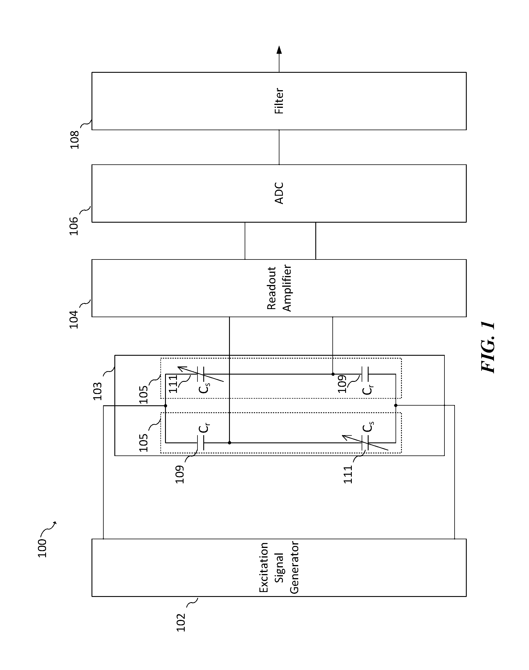
[0048]In the first embodiment, the slope of the excitation 302 is reduced in order to avoid overly stimulating the resonant condition of MEMS sensor 103. FIG. 4 illustrates a comparison between a square wave excitation signal 402, and wave shaped excitation signal 404 that are used to stimulate MEMS sensor at input port Vex. As shown, output waveform 406 represents high amplitude ringing due to a square wave input 402 that contains steep slope at rising and falling edges because of the resonances stimulated by square wave excitation signal 402 having steep rising and falling edges causes resonance. The output waveform 408, on the other hand, represents the response from the wave shaped excitation signal 404 and exhibits very little ringing due to smooth edges at the falling and rising portion of the input as well as the transition region to the flat region. The smooth edges at the rising and falling portion of the excitation signal 404 reduces the effect of resonances due to high Q ...

second embodiment

[0062]In the second embodiment, ADC 106 varies its internal sampling clock signal by a pseudo-random jitter to mitigate the effect of ringing noise. This pseudo-random jitter is provided by varying the timing of the rising and / or falling edge of the sampling clock on which ADC 106 derives its timing reference. Accordingly, the systematic ringing error of the outputs of the sensor 103 is thus converted to a wide-band signal, which the filter 108 may suppress by, for example, averaging many digital samples to form each combined measurement sample.

[0063]FIG. 8 illustrates an example ADC 800 that may be used as the ADC 106 of FIG. 1 to generate a clock signal having pseudo-random jitter. ADC 800 includes a variable clock generator 804, a frequency divider 806, and a sampling unit 808.

[0064]The variable clock generator 804 generates a variable clock signal that has a pseudo-random jitter. The variable clock generator 804 includes this pseudo-random jitter in the variable clock signal by ...

third embodiment

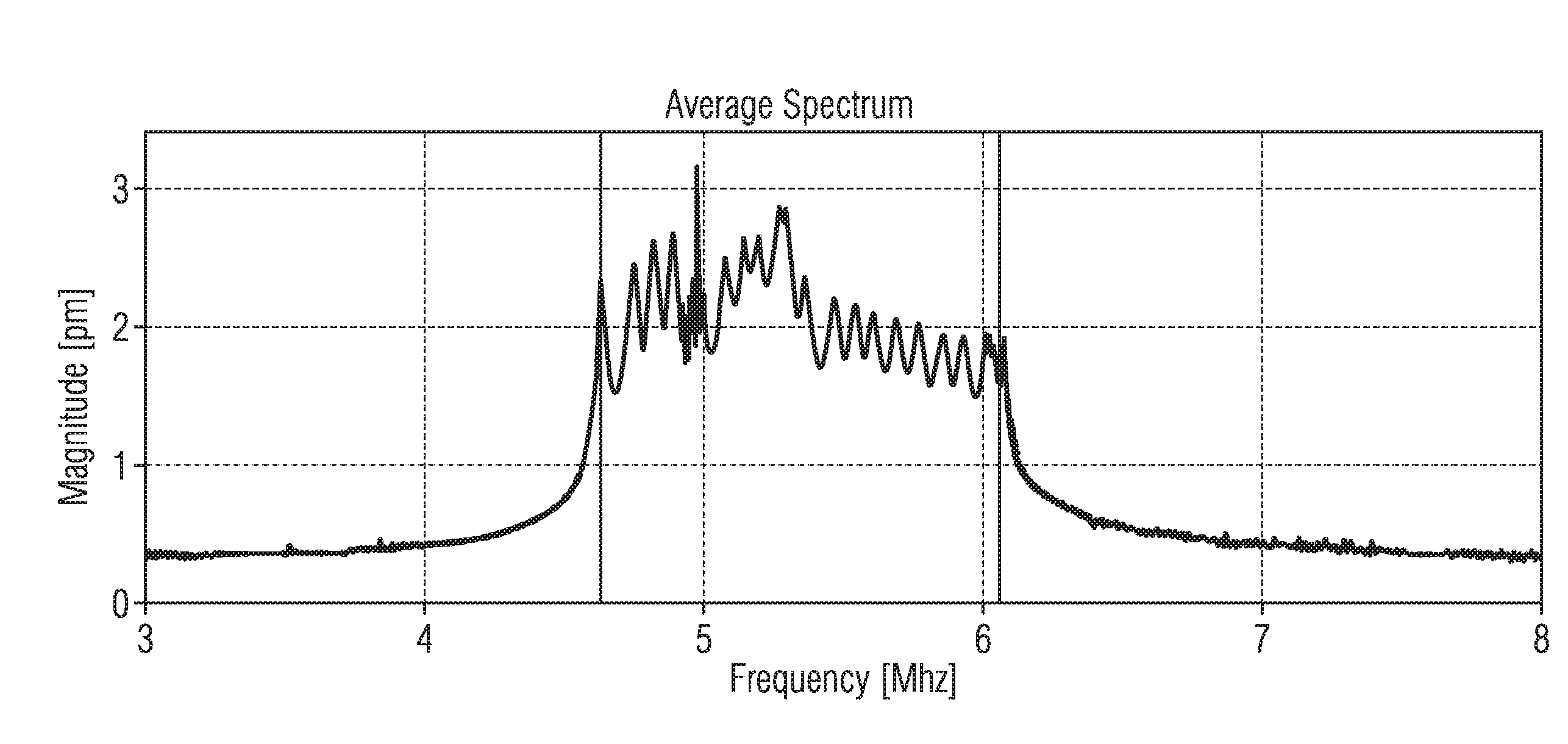
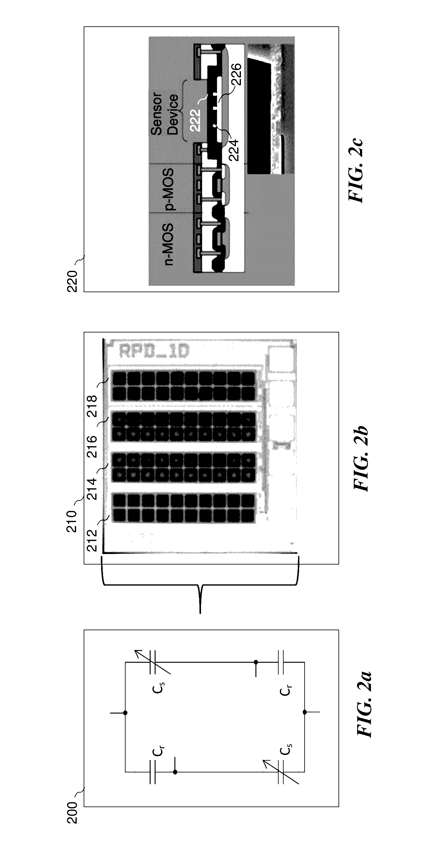
[0091]In the third embodiment, the MEMS pressure sensor is implemented using an array or MEMS pressure sensors that have varying dimensions, such that each of the MEMS pressure sensors resonate at different frequencies. Hence, when the MEMS pressure sensors are stimulated by the excitation signal, the amplitude of the ringing may be reduced at various times due to the various resonant responses being out of phase with each other. This is the case since the individual resonance signals are added, for example, by connecting the sensors electrically in parallel. In order to reduce the ringing caused by an underdamped response of the MEMS pressure sensors are designed with an array of MEMS capacitive pressure sensors. Each capacitive pressure sensor is designed with different dimensions such that the harmonic frequency for each capacitive sensor element is different than others in the array. When excited with a square wave excitation signal, each capacitive sensor element will ring with...


PUM


Abstract

In accordance with an embodiment, a method of performing a measurement with a capacitive sensor includes generating a periodic excitation signal that includes a series of pulses and smoothing edge transitions of the series of pulses to form a shaped periodic excitation signal that includes a flat region between the smoothed edge transitions. The method further includes providing the shaped periodic excitation signal to a first port of the capacitive sensor and measuring a signal provided by a second port of the capacitive sensor.

Description

[0001]This application claims the benefit of U.S. Provisional Application No. 62 / 150,027, filed on Apr. 20, 2015, which application is hereby incorporated herein by reference in its entirety.CROSS-REFERENCE TO RELATED APPLICATIONS[0002]This patent application further relates to the following co-pending and commonly assigned U.S. patent applications that also claim the benefit of U.S. Provisional Application No. 62 / 150,027, filed on Apr. 20, 2015: Ser. No.______, filed on entitled (Attorney Docket Number 2015 P 50162 US), Ser. No.______, filed on entitled (Attorney Docket Number 2015 P 50088 US), and Ser. No.______, filed on entitled (Attorney Docket Number 2015 P 50089 US), which applications are hereby incorporated herein by reference in their entirety.TECHNICAL FIELD[0003]The present invention relates generally to sensor systems, and, in particular embodiments, to a system and method for a capacitive sensor.BACKGROUND[0004]Microelectromechanical Systems (MEMS), which in general in...

Claims


Application Information

Patent Timeline
Patent Type & Authority Applications(United States)
IPC IPC(8): G01R27/26
CPCG01R27/2605G01L1/144G01D5/24G01L9/0072G01R15/16G01R17/00G01R29/02B81B2201/0264
Inventor WIESBAUER, ANDREASEBNER, CHRISTIANROMANI, ERNESTOMECHNIG, STEPHANPANOV, GEORGIJENKNER, CHRISTIANMUEHLBACHER, BENNO
Owner INFINEON TECH AG
Why Eureka
Try Eureka