Polycarbonate lens for eyewear and method for manufacturing the same

a polycarbonate lens and lens technology, applied in the field of polycarbonate lens for eyewear, can solve the problems of difficult to contain adhesive, difficult to control density, easy to strip the protective layer on the convex surface in part, etc., to reduce the interference pattern, prevent crack generation, and reduce the interference pattern of the lens

Inactive Publication Date: 2016-10-20
MIYOSHI INDAL ENTERPRISE
View PDF6 Cites 4 Cited by
  • Summary
  • Abstract
  • Description
  • Claims
  • Application Information

AI Technical Summary

Benefits of technology

[0016]According to another aspect of the present invention, the polycarbonate lens for eyewear may include the acrylic coat layer on the convex surface of the polycarbonate protective layer constituting polarizing material, and the hard coat layer is provided on the acrylic coat layer in order to reduce interference pattern on the lens surface by effect of the multilayer and prevent crack generation during bending into lens shape and injection molding of polycarbonate. Also, the hard coat layer preferably includes a primer layer and a hard coat layer in order to reduce interference pattern of the lens.
[0017]Moreover, according to another aspect of the present invention, the polycarbonate lens for eyewear may further include tinted gradation on the polarized material and the hard coat layer to provide the lens with no interference pattern, and thus, the polycarbonate lens for eyewear does not need mirror coating.

Problems solved by technology

This conventional method is vulnerable when using, since dyeable coating is softer than hard coating which is usually used, or this conventional method is difficult to control density, since the other side is deleted by grinding when using semi lens, for example, color of the other side of lens would pass away when dyeable coating and tinting is performed at semi stage.
However, this method in prior art has a problem that protective layer on the convex surface is easily stripped in part by elongation stress during bending process.
Additionally, since it is difficult to contain adhesive in removable protective layer because of weak chemical resistance of polycarbonate, perimeter of protective layer is easily stripped in part due to weak adhesive power.
However, because thickness of common hard coat layer is thin, only 1-2 μm, it is difficult to obtain high-hardness by simply adding the hard coat on a surface of low-hardness polycarbonate.
Therefore, it has a problem of arising a crack on convex surface when bending polycarbonate material disposed with hard coating layer to a form of lens which provides a specific curvature.
Moreover, since visible light of polycarbonate has high refractive index of 1.585, the difference of refractive index tends to cause interference pattern when hard coat of 1-2 μm is added.
However, as the polarized lens tinted gradation has fashionability more than sporting use, mirror coating on the surface reduces the additional value by hiding gradation.

Method used


Image

  • Polycarbonate lens for eyewear and method for manufacturing the same
  • Polycarbonate lens for eyewear and method for manufacturing the same
  • Polycarbonate lens for eyewear and method for manufacturing the same

Examples


first embodiment

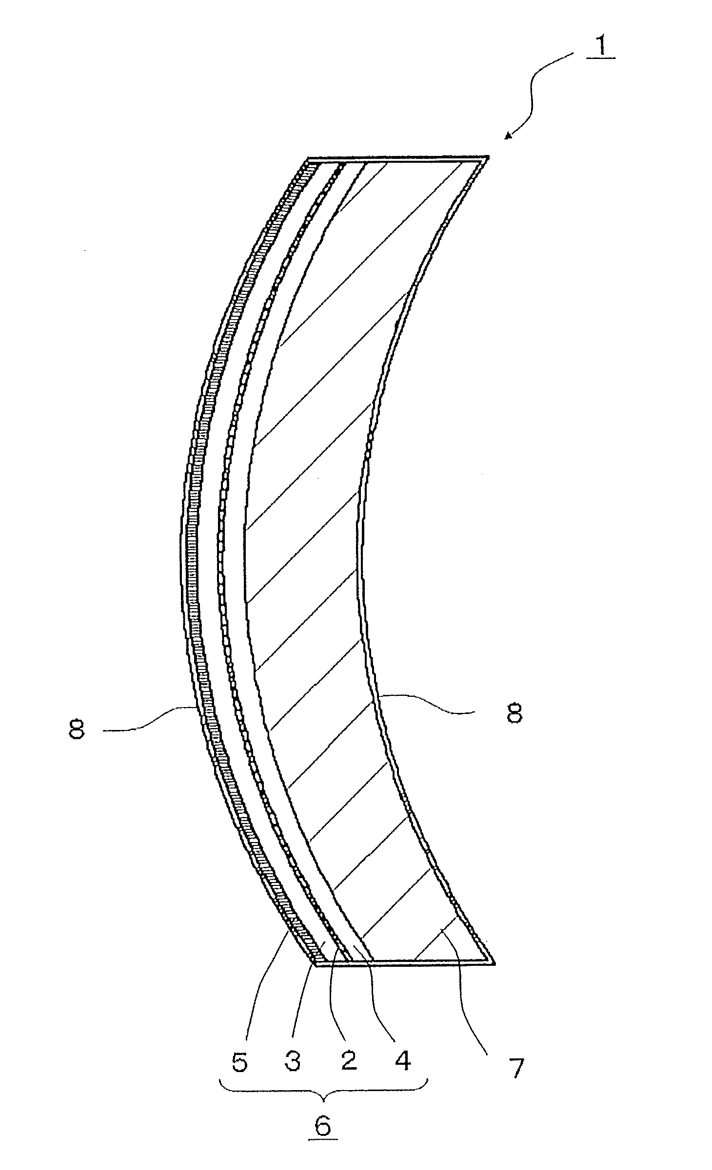
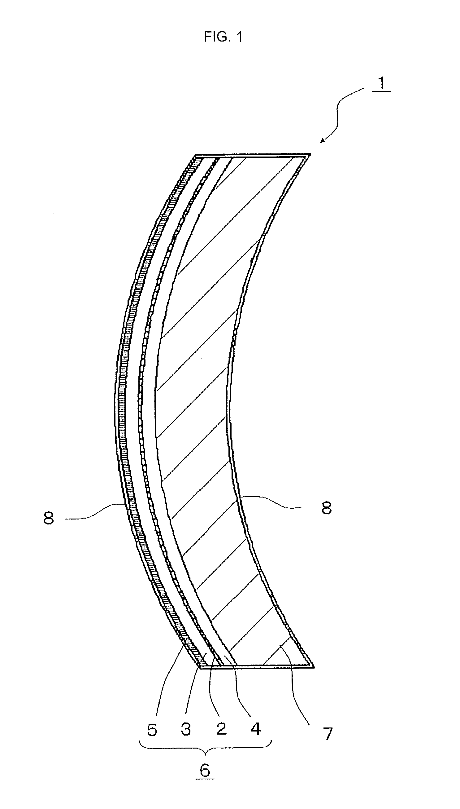
[0026]the present invention will be described with reference to FIG. 1.

[0027]Referring to FIG. 1, the polarized polycarbonate lens for eyewear 1 configured of polarized layer 2 includes polycarbonate protective layers 3, 4 on the polarized layer 2, an acrylic coat layer 5 is formed on the convex surface of the polycarbonate protective layer 3 to form a polarized material 6 protected by the acrylic coat layer 5. Also the polarized material has lens shape with integrally bonding polycarbonate molded part 7, which has an identical chemical structure with polycarbonate protective layer 4, by injection molding on concave surface of polarizing material 6, that is to say the polycarbonate protective layer 4. Also, the polycarbonate lens is configured further to include a hard coat layer 8 over the whole surface of the lens from the convex surface of acrylic coat layer to concave surface of the polycarbonate molded part 7.

[0028]The reason why acrylic coat layer 5 is disposed only on the sur...

second embodiment

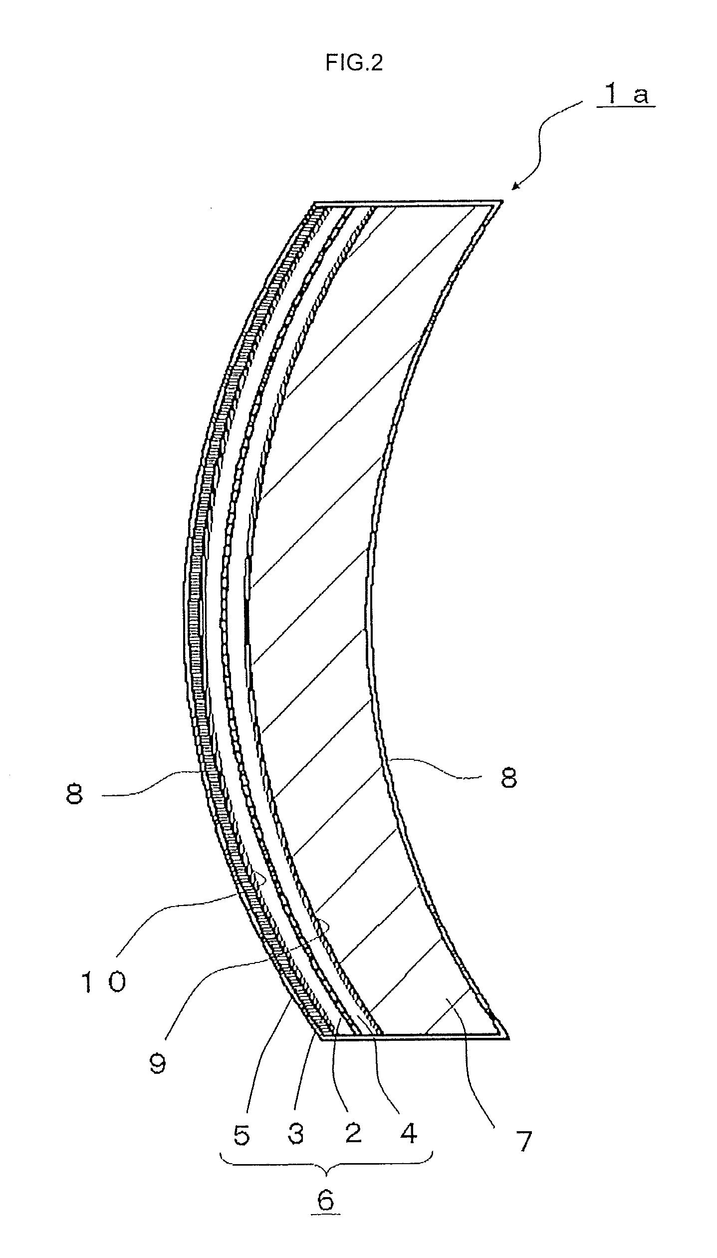
[0038]The polarized material 6 bent in the third step S3 is disposed on tinted layers 12, 13 on the convex and the concave surface of polarized material 6 tinted in dyeing liquid in the following fourth step S4. The tinted layers 12, 13 are tinted by means of immersing in dyeing liquid with up-and-down to obtain gradation pattern. Also, the tinted layer 13 on the acrylic coat layer 5, as described in aforementioned second embodiment, forms layer on convex surface of polycarbonate protective layer 3 penetrating and tinting this acrylic coat layer 5 when tinting the convex acrylic coat layer 5 consisting the polarized material 6. Additionally, tinting can be chosen by design of polycarbonate lens for eyewear without sticking gradation pattern.

[0039]The figure shows colored lens immersed with shaking up-and-down in dyeing liquid with left side of lens aimed downward, and the figure shows tinted layers 12 and 13 in coloring step of the fourth step S4, with the layers are thick in left s...

embodiment 1

[0058]According to table 1 that shows evaluation of 6 samples above, samples 4 to 6 of polycarbonate lenses for eyewear, which include an acrylic coat layer on the surface of the polycarbonate protective layer on one side surface thereof, and further include a hard coat layer on the surface of the acrylic coat layer, as described in the embodiment 1 and the following embodiments, have better “surface hardness” comparison with samples 1 to 3, which do not include. Moreover, samples 5 and 6 with a hard coat layer of two-layer including a primer layer have better “surface hardness”. In addition, as to “interference pattern”, the lens with both of an acrylic coat layer and a primer layer has better result, regardless whether the gradation dyeing is performed.


PUM

PropertyMeasurementUnit
thicknessaaaaaaaaaa
refractive indexaaaaaaaaaa
thicknessaaaaaaaaaa

Abstract

The invention relates to a polarized polycarbonate lens for eyewear including protective layers having polarizing function on both sides of a polarized layers, a polarized material with an acrylic coat layer on the convex surface of protective layer so as to be formed into lens shape, a molded part formed integrally on the concave surface of the polarized material, and a hard coat layer on the surface of the acrylic coat layer on the convex surface. The lens has features of less interference pattern and less crack generation during bending step into lens shape and forming step. Moreover, the hard coat layer may be two-layer including a primer layer to generate less interference pattern and cracks. Additionally, this lens does not generate interference pattern even when it includes tinted gradation and a hard coat layer, and the lens does not need mirror coating on the surface.

Description

BACKGROUND OF THE INVENTION[0001]1. Field of the Invention[0002]The present invention relates to a polycarbonate lens for eyewear including polycarbonate protective layers on the both sides of a polarized layer with polarizing function, an acrylic coat layer on a polarized material, and a polycarbonate molded part formed integrally on the polarized material. Also relates to a method for manufacturing of the polycarbonate lens for eyewear by means of disposing tinted layer thereon.[0003]2. Description of the Background Art[0004]Polarized polycarbonate lenses which include multi-layer sheet of polycarbonate formed on rear side by injection molding is excelled in shock resistance, sunglass function and polarizing function, and is preferably used in outdoor sports, especially in marine sports, in order to avoid glare of water surface reflection. Moreover, products with improved design, which have gradation by tinting on the polycarbonate lens, are provided.[0005]A conventional method fo...

Claims


Application Information

Patent Timeline
Patent Type & Authority Applications(United States)
IPC IPC(8): G02C7/12G02C7/10B29D11/00G02B1/14
CPCG02C7/12G02B1/14G02C7/105B29D11/00644B29K2105/256B29D11/00923G02C2202/16B29K2069/00B29D11/00432
Inventor MIYOSHI, KAZUYUKI
Owner MIYOSHI INDAL ENTERPRISE
Why Eureka
Try Eureka