
Method of making antiglare film, antiglare film, polarizing plate, image display device, and transmissive/semi-transmissive liquid crystal display

a liquid crystal display and film technology, applied in the direction of polarizing elements, diffusing elements, instruments, etc., can solve the problems of inability to achieve antiglare performance, additional equipment cost, yield loss, etc., and achieve low scintillation, high front white brightness, and high contrast

Active Publication Date: 2010-09-30
FUJIFILM CORP
View PDF8 Cites 24 Cited by
  • Summary
  • Abstract
  • Description
  • Claims
  • Application Information

AI Technical Summary

Benefits of technology

[0008]An object of the invention is to provide an antiglare film and a polarizing plate that contribute to the improvement of display qualities and thickness reduction of image display devices, such as LCDs, and a method for making the antiglare film easily and at low cost.
[0009]Another object of the invention is to provide an image display device with high front white brightness, high contrast, low scintillation, and low interference, such as a Moire phenomenon.
[0019]In application to image display devices, the antiglare film of the invention provides high front white brightness, high contrast, low scintillation, and reduced interference patterns, such as Moire.

Problems solved by technology

The technique of WO 2006 / 88202 requires at least two coating operations to obtain a desired surface profile, which is expected to involve additional cost of equipment and loss of yield.
That is, to control only the Ra of the active ray-cured resin layer invites reduction in contrast or causes scintillation or is incapable of achieving antiglare performance without inducing contrast reduction or scintillation.

Method used


Image

  • Method of making antiglare film, antiglare film, polarizing plate, image display device, and transmissive/semi-transmissive liquid crystal display
  • Method of making antiglare film, antiglare film, polarizing plate, image display device, and transmissive/semi-transmissive liquid crystal display
  • Method of making antiglare film, antiglare film, polarizing plate, image display device, and transmissive/semi-transmissive liquid crystal display

Examples


examples

[0161]The invention will now be illustrated in greater detail with reference to Examples.

[A] Preparation of Transparent Base

[0162]Dopes A to O were prepared according to the formulations of Table 1. Transparent bases 1 through 17 were prepared by co-casting three different dopes to make a surface dope / basal dope / surface dope structure as shown in Table 2. The solid content of the dope for a basal layer (dope B) and the solid content of the dopes for surface layers (dopes A and C to O) were adjusted to 23 mass % and 18 mass %, respectively, with a 90 / 10 by mass mixed solvent of methylene chloride and methanol. The refractive index of the particles used in the dopes was measured as described supra.

[0163]Transparent bases 1 to 15 and 17 were made using the casting equipment illustrated in FIG. 3, which had a mirror finished casting drum cooled to −10° C. The three dopes were co-cast with the dope for surface layer 1 in contact with the rotating drum, chilled by the drum to a gel while ...


PUM

PropertyMeasurementUnit
primary particle sizeaaaaaaaaaa
height Rtaaaaaaaaaa

Abstract

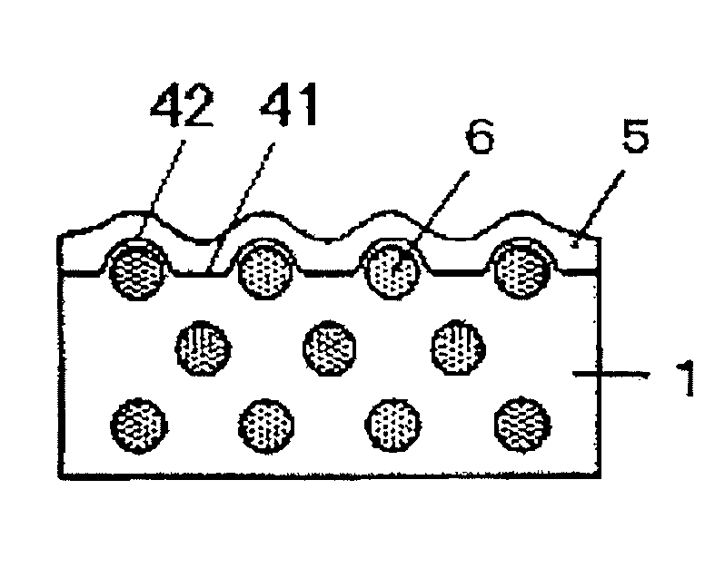
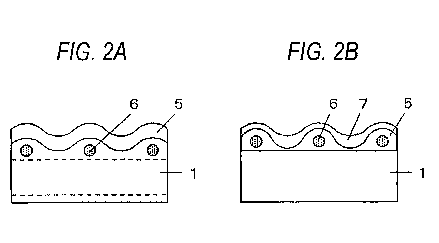
In a method for making an antiglare film including the casting, the releasing, the drying, the applying and the curing as defined herein, the transparent particles have an average primary particle size of greater than 2.5 μm and not greater than 12 μm, the transparent base has on at least one side thereof flat portions substantially parallel to a film-forming plane and rounded protrusions arising from the transparent particles, the protrusions having a maximum height Rt from the flat portions of from 1 to 15 μm, and the cured layer has an average thickness of from 1 to 15.0 μm and a surface profile with an arithmetic average roughness Ra, a mean spacing between peaks Sm, and an average slope θa, all as measured in accordance with JIS B0601, satisfying the relationships (1) to (3) as defined herein.

Description

CROSS-REFERENCE TO RELATED APPLICATIONS[0001]This application claims the benefit of Japanese Patent Application JP 2009-083794, filed Mar. 30, 2009, the entire content of which is hereby incorporated by reference, the same as if set forth at length.FIELD OF THE INVENTION[0002]This invention relates to a method of making an antiglare film, an antiglare film, a polarizing plate, an image display device, and a transmissive or semi-transmissive liquid crystal display device.BACKGROUND OF THE INVENTION[0003]Liquid crystal displays (LCDs) have recently enjoyed wide use because of small thickness, light weight, and low power consumption. An LCD includes a liquid crystal cell and a polarizing plate. A polarizing plate is usually composed of protective films and a polarizing film and obtained by stretching a polyvinyl alcohol film dyed with iodine to make a polarizing film and laminating a protective film to both sides of the polarizing film. A transmissive LCD has a polarizing plate on both...

Claims


Application Information

Patent Timeline
Patent Type & Authority Applications(United States)
IPC IPC(8): G02F1/1335G02B5/02G02B1/12G02B5/30B05D5/06
CPCG02F1/133502G02B5/02
Inventor WATANABE, JUNYONEYAMA, HIROYUKISUZUKI, TAKATO
Owner FUJIFILM CORP
Learn More