
Differentiated control method of the cascaded active power filter

Inactive Publication Date: 2016-10-20
CHEN JUNLING
View PDF1 Cites 13 Cited by
  • Summary
  • Abstract
  • Description
  • Claims
  • Application Information

AI Technical Summary

Benefits of technology

The present invention provides a control method for a cascaded active power filter that can reduce system switch loss, ensure DC capacitor voltage balance, and improve harmonic filtering performance. The method selects high frequency links based on a designated cycle, resulting in relatively uniform average switch loss and easier heat dissipation design. The voltage output of the cascaded multilevel converter has a large ratio of fundamental wave voltage, which reduces switch loss. The DC capacitor voltage balancing algorithm is simple and fast, without overshoot or oscillations and adjusts pulse of each link only on the sequence to avoid affecting output characteristics of the converter.

Problems solved by technology

The significant increase of apparatus capacity and the diversity of control methods generate high grid voltage harmonic distortion and current harmonic distortion effects which pose significant challenges and concerns.
Specifically, harmonics generated by nonlinear loads cause harmonic pollution.
In particular, increasing the switch frequency of all the devices will greatly increase the switch loss of the system, thereby increasing the cooling requirements of the system, and decreasing the cost-effectiveness of the system.
Additionally, this system creates a DC capacitor voltage imbalance in the cascaded APF, which may pose a safety hazard: switch loss and DC capacitor voltage balancing control creates a bottleneck that restricts the application of the cascaded APF.
However, the voltage balancing effect is greatly affected by the control parameters, and overshoot and oscillation are produced in the voltage balancing process.
However, this arrangement increases the cost and volume of the system, and greatly increased the complexity of control.
Importantly, these patents did not address the fact that each switch device adopts a different switch frequency.

Method used


Image

  • Differentiated control method of the cascaded active power filter
  • Differentiated control method of the cascaded active power filter

Examples


Embodiment Construction

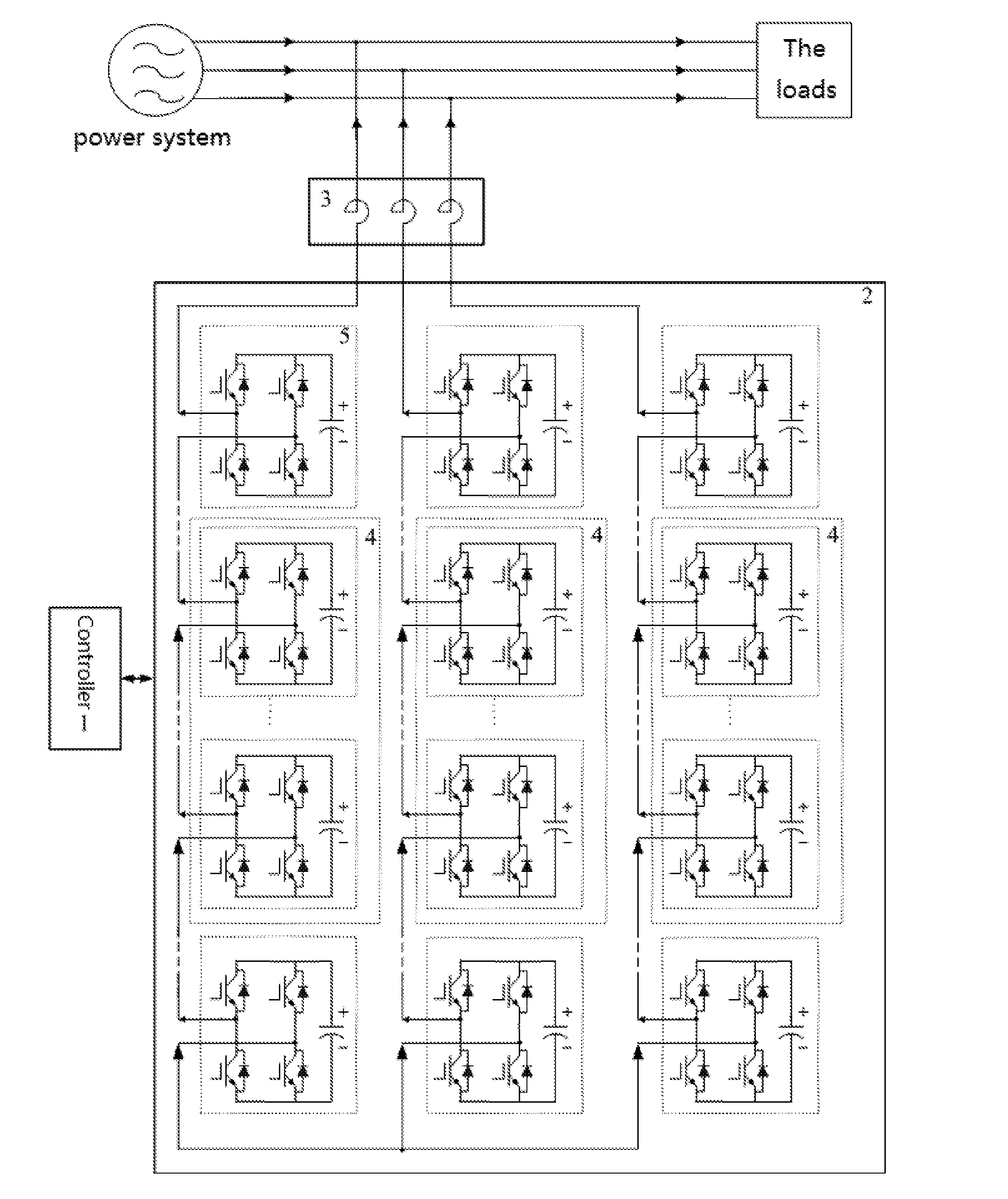
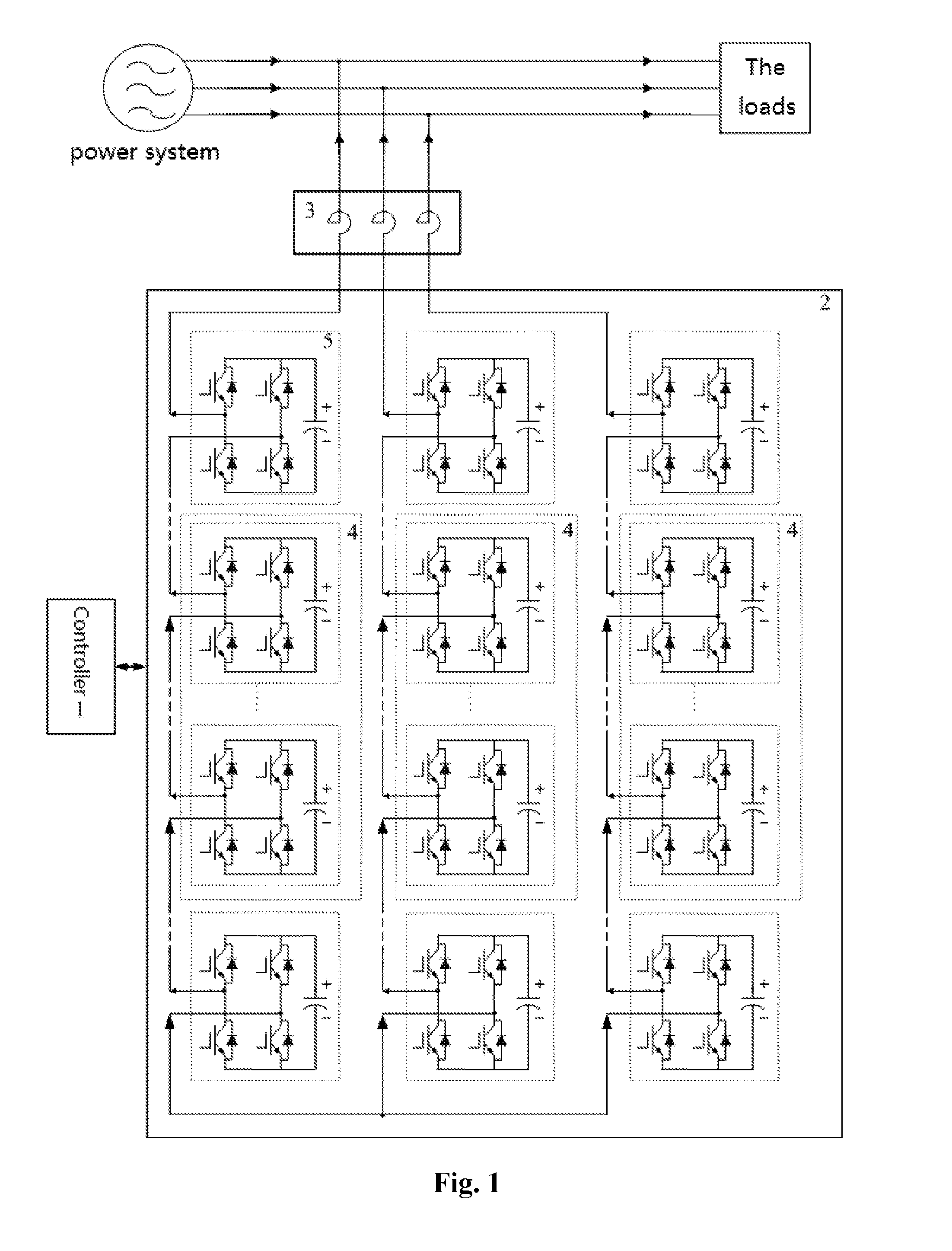
[0029]FIG. 1, discussed below, and the various embodiments used to describe the principles of the present invention in this patent document are by way of illustration only and should not be construed in any way to limit the scope of the invention. Those skilled in the art will understand that the principles of the present invention may be implemented in any suitably cascaded active power filter.

[0030]As shown in FIG. 1:

[0031]FIG. 1 illustrates a differentiated control method structure of the cascaded active power filter comprising a controller 1, the cascaded multilevel converter 2 used to produce voltage compensation, and the reactor 3, which generates compensation current that is connected to the power grid. The present invention operates according to the power grid's requirements of reactive power compensation and harmonic control. Specifically, the controller 1 computes the voltage that needs to be generated by the cascaded multilevel converter 2. The cascaded multilevel convert...


PUM


Abstract

The present invention relates to a differentiated control method of the cascaded active power filter, wherein the cascaded links are divided into low frequency links and high frequency links; wherein low frequency links are used to generate the fundamental voltage generated by the cascaded multilevel converter; wherein high frequency links are used to produce different, separate voltage from the aforementioned fundamental voltage generated by the cascaded multilevel converter; wherein according to the given cycle, some links are selected circularly from cascaded links as the high frequency links; wherein in the control cycle, each phase links with the maximum and minimum DC capacitor voltage, as well as those links that the pulse width modulation (PWM) combination discharge and charge most to DC capacitor are found out.

Description

TECHNICAL FIELD[0001]The present invention relates to the fields of reactive power compensation and harmonic suppression in the power system, and involves a differentiated control method of the cascaded active power filter.BACKGROUND[0002]With the development of electronic power technology, many non-linear electronic power devices are widely applied to power systems. The significant increase of apparatus capacity and the diversity of control methods generate high grid voltage harmonic distortion and current harmonic distortion effects which pose significant challenges and concerns. Specifically, harmonics generated by nonlinear loads cause harmonic pollution. Consequently, active power filter (APF) is becoming the focal point of the current research and application in the field of reactive power compensation and harmonic filtering. Compared to the traditional passive power filter, APF has the following advantages and features:[0003]1. It has a variety of compensatory functions. For ...

Claims


Application Information

Patent Timeline
IPC IPC(8): H02J3/18H02M1/12H02M7/219H02M1/42
CPCH02J3/1857H02M7/219H02M1/12H02M1/4233Y02E40/20H02M1/327H02M7/4835H02J3/01
Inventor YUAN, XUEFEI
Owner CHEN JUNLING
Learn More