Unlock instant, AI-driven research and patent intelligence for your innovation.

Electromagnetic Energy Harvesting Using Complementary Split-Ring Resonators

Inactive Publication Date: 2016-10-20
ALAVIKIA BABAK +2
View PDF7 Cites 28 Cited by
  • Summary
  • Abstract
  • Description
  • Claims
  • Application Information

AI Technical Summary

Benefits of technology

The G-CSRR structures described in this patent have several advantages over classical antennas. These structures have higher power conversion efficiency and can work over wider ranges of frequencies. They can be placed close to each other, allowing for a smaller overall size. Additionally, G-CSRR structures can be placed over conducting surfaces without interfering with any wireless devices contained within the surface.

Problems solved by technology

Additionally, their performance is limited to the type of semiconductor material used.
Moreover, photovoltaics depend on direct sunlight illuminations and therefore it cannot function at night time when the sun is down.
However, the total footprint of the array is constrained by physical area of the device or land.

Method used


Image

  • Electromagnetic Energy Harvesting Using Complementary Split-Ring Resonators
  • Electromagnetic Energy Harvesting Using Complementary Split-Ring Resonators
  • Electromagnetic Energy Harvesting Using Complementary Split-Ring Resonators

Examples


Embodiment Construction

[0050]The invention describes an electromagnetic energy collector based on Complementary Split Ring Resonators (CSRRs). Since there can be a variety of permutations and embodiments of the present invention, certain embodiments will be illustrated and described with reference to the accompanying drawings. This, however, by no means restricts the present invention to certain embodiments, and shall be construed as including all permutations, equivalents, and substitutes covered by the spirit and scope of the present invention.

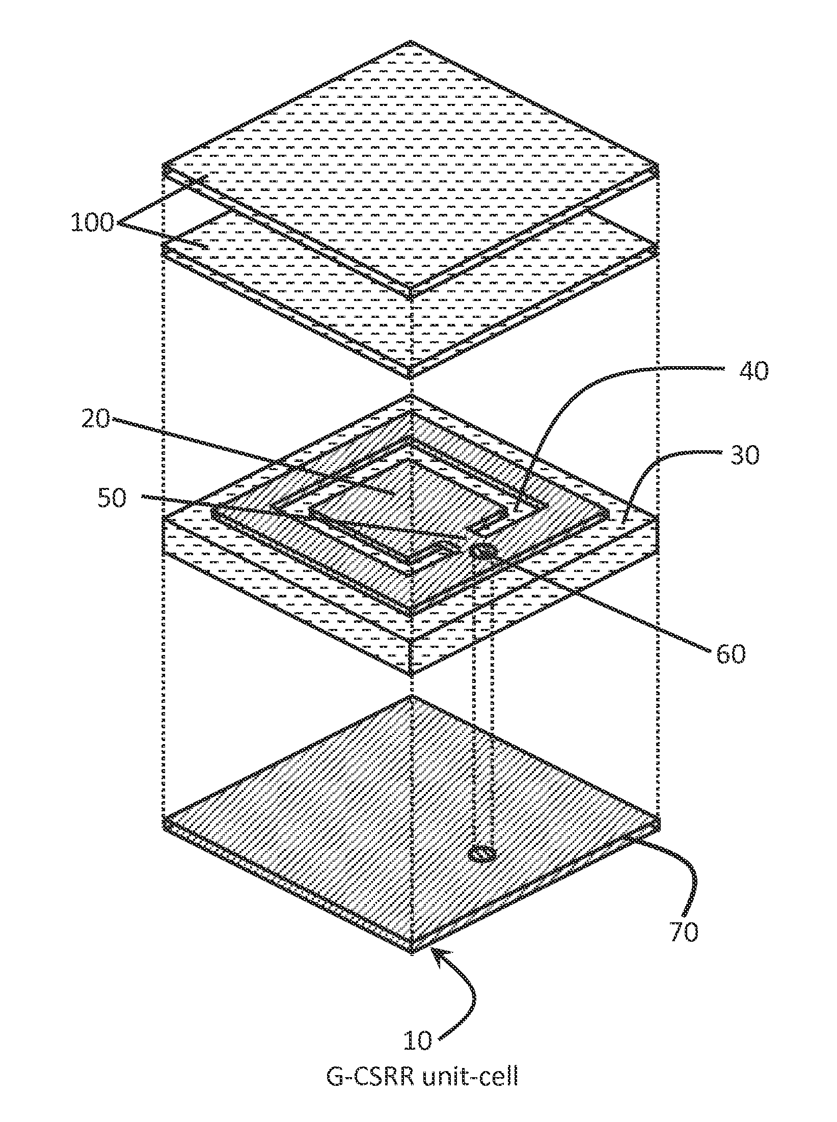
[0051]A CSRR structure comprising metallic (conducting) CSRR Patch(es) 20 deposited or printed on a non-conductive medium host herein referred as Dielectric Substrate 30 is shown in FIG. 3. The CSRR Patch(es) 20 is a planar conducting structure with a center island separated from the surrounding planes by plurality of broken Etched Loop(s) 40. The center conducting island is connected to its surroundings through narrow Bridge(s) 50. The CSRR Patch(es) 20 can take ...


PUM


Abstract

The current invention provides Ground-backed Complementary Split Ring Resonators (G-CSRR) as a new class of energy collectors and transmitters for electromagnetic energy harvesting in general and wireless power transfer applications in particular. The G-CSRR structure has low profile, low fabrication cost, efficient for wide range of illumination angles and can be placed on metallic surfaces.

Description

CROSS-REFERENCE TO RELATED APPLICATIONS[0001]This invention claims priority to pending U.S. Provisional Patent Application No. 61 / 923,822, entitled Electromagnetic Energy Harvesting using Complementary Split-Ring Resonators, filed on Jan. 6, 2014, the contents of which are herein incorporated by reference.FIELD OF THE INVENTION[0002]This invention relates generally to electromagnetic energy harvesting systems, and particularly to wireless power transfer systems and rectenna systems operating at both the microwave and terahertz frequency regimes. In addition, the invention relates to applications where electric energy is needed such as Space Solar Power (SSP) systems, Radio Frequency Identification (RFID) systems, charging batteries, etc.BACKGROUND OF THE INVENTION[0003]In every minute enough sunlight reaches the earth's surface to meet the world's energy demand for an entire year. Due to this enormous amount of electromagnetic energy emitted by the sun, researchers have focused on d...

Claims


Application Information

Patent Timeline
IPC IPC(8): H02J50/27H02J50/40H01Q21/06H01Q9/04H01Q1/38
CPCH02J50/27H01Q9/0407H02J50/40H01Q21/065H01Q1/38H01Q1/248H02J50/001
Inventor ALAVIKIA, BABAKALMONEEF, THAMERRAMAHI, OMAR M.
Owner ALAVIKIA BABAK