Optical coherence tomography system

a coherence tomography and optical coherence technology, applied in the field of optical coherence tomography systems, can solve the problems of unable to easily accept additional components and add an additional polarization-oct-image capture function, and the components such as pm fibers, wave plates, and eoms are extremely expensive, and achieve the effect of low cost, easy addition of polarization-oct-capturing functions, and small siz

Active Publication Date: 2016-10-27
CANON KK
View PDF0 Cites 1 Cited by
  • Summary
  • Abstract
  • Description
  • Claims
  • Application Information

AI Technical Summary

Benefits of technology

[0012]In view of these problems, one embodiment of the present invention provides a polarization-sensitive OCT system that can be formed in a small size at a low cost. Furthermore, one embodiment of the present invention provides a polarization-sensitive OCT system that can easily add a polarization-OCT-capturing function to a conventional OCT system.

Problems solved by technology

Components such as PM fibers, wave plates, and EOMs, however, are extremely expensive and consequently make the polarization-sensitive OCT expensive.
Moreover, conventional OCT systems are unable to easily accept additional components and an additional polarization-OCT-image capturing function.
Thus, medical institutions that have already had a conventional OCT system have to purchase a new system, causing a heavy burden.
Furthermore, a large space is required to install two OCT systems.
This OCT system can facilitate polarization adjustment but cannot be formed at a low cost due to the use of expensive optical elements.
However, as in the system of NPL 1, the polarization-sensitive OCT system cannot be formed at a low cost because of a very expensive EOM.
The use of the PMF reduces the size of the system but prevents cost reduction of the system because the PMF is a very expensive optical component.
In addition, the polarization-sensitive OCT systems of the above-described NPLs have configurations basically different from the configuration of conventional OCT systems and thus conventional OCT systems are highly unlikely to be extensible, specifically, to be changed into polarization-sensitive OCT systems.
Changing conventional OCT systems into the above-described polarization-sensitive OCT systems involves replacement or addition of most of the components, making it impossible to easily add functions.

Method used


Image

  • Optical coherence tomography system
  • Optical coherence tomography system
  • Optical coherence tomography system

Examples


first embodiment

[0025]A configuration of a polarization-sensitive OCT system according to the embodiment will be described referring to FIG. 1.

[Entire Configuration of System]

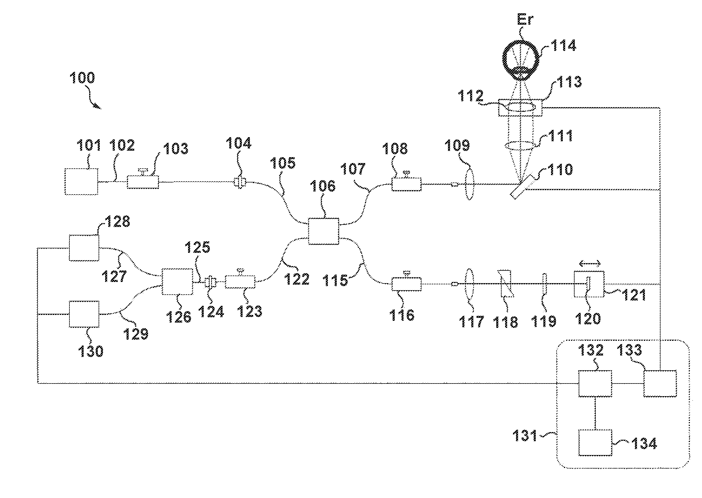
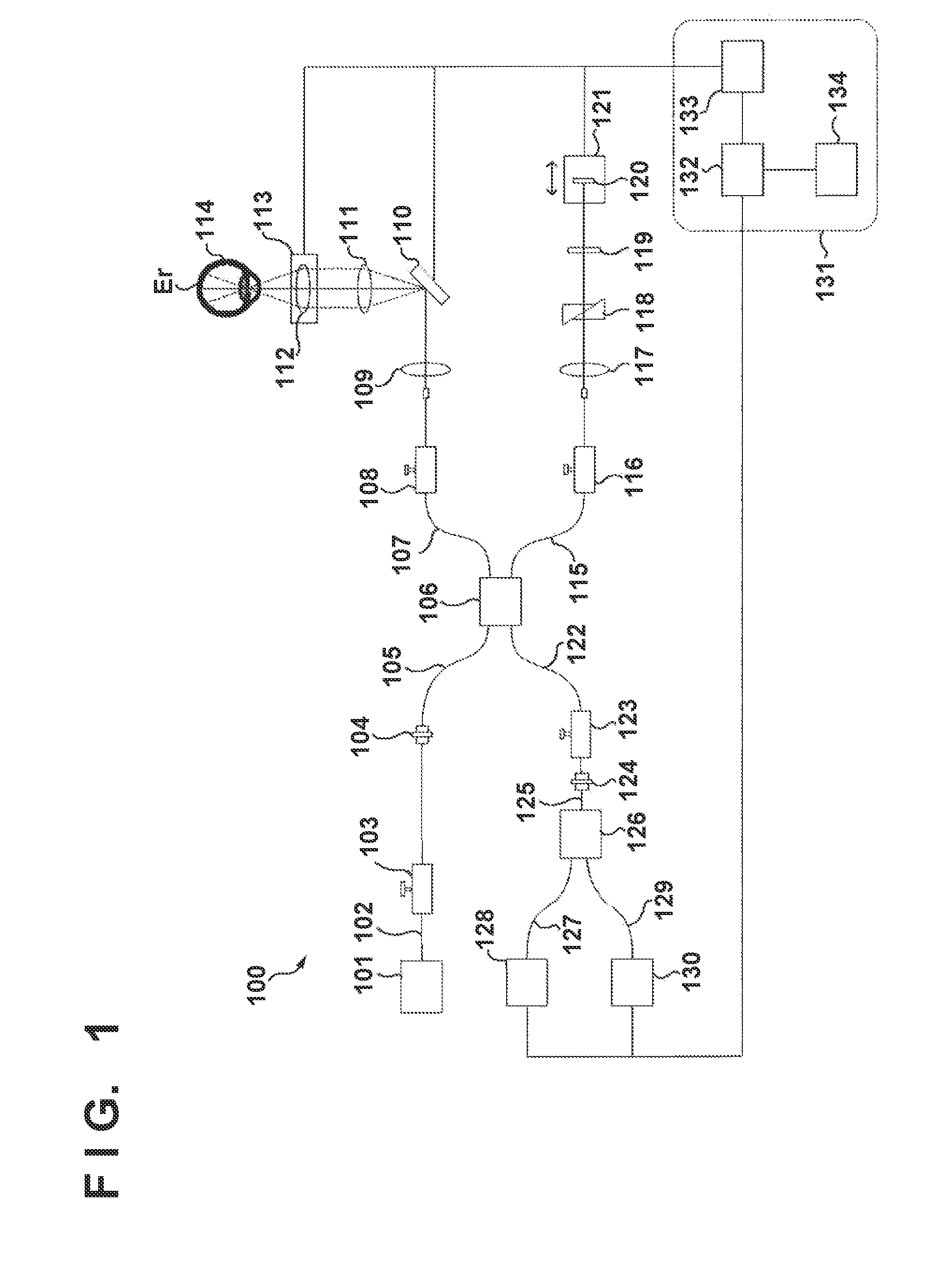
[0026]FIG. 1 is a schematic diagram of the entire configuration of the polarization-sensitive OCT system according to the embodiment. In this embodiment, the configuration of a spectral domain (SD)-OCT system is described.

100>

[0027]The Polarization-Sensitive OCT System 100 according to the first embodiment includes a plurality of single mode fibers and a plurality of polarization controllers, wherein at least one of the plurality of polarization controllers is disposed on each of the fibers of the interferometer, which include a fiber (107) for a measurement light beam, a fiber (115) for a reference light beam, and a fiber (122) near a detector. An image forming unit (132) determines a pixel value from a data set including two orthogonal polarization components concurrently obtained at substantially identical spatial positions...

second embodiment

[0045]In this embodiment, referring to FIGS. 5 and 6, a method for forming a polarization-sensitive OCT system by adding components to a conventional OCT system will be described. In this embodiment, an SS-OCT is used for a light source 501, as an example. Since the basic configuration of an SS-OCT is a publicly-known configuration, the SS-OCT is not described in detail here.

[0046]FIG. 5 illustrates a conventional SS-OCT system. The configuration shown by reference numerals 503 to 518, 520 and 527 to 530 in FIG. 5 are similar to the configuration shown by reference numerals 104 to 119, 121 and 131 to 134 in FIG. 1 respectively. In FIG. 5, 519 are mirrors, 521, 524 and 525 are SM fibers, 523 is a polarization beam splitter as an example of polarization dividing means, 526 is a detector and 531 is a collimator. A detector 526 and SM fibers 524 and 525 are detachable from each other. Additional components are attached only to a portion on an SM fiber 502, which guides light emitted fro...


PUM


Abstract

In a polarization-sensitive optical coherence tomography system, an interferometer includes single mode fibers and a plurality of polarization controllers. At least one of the plurality of polarization controllers is disposed on each of the fibers of the interferometer. The fibers include a fiber for sample light beam, a fiber for reference light beam, and a fiber for detection light beam. An image forming unit determines a pixel value from a data set consists of two orthogonal polarization components simultaneously obtained at substantially identical spatial positions of a test sample, wherein a measurement light beam has static single polarization state.

Description

TECHNICAL FIELD[0001]The present invention relates to optical coherence tomography systems, particularly, to an optical coherence tomography system that can capture information on polarization characteristics of a target eye.BACKGROUND ART[0002]In these years, optical coherence tomography (OCT) systems (referred to as OCT systems, below) that utilize interference due to low coherence light have been practically used. The OCT systems can noninvasively capture a tomograph image of a test sample with high resolution. The OCT systems have thus been growing into indispensable systems, particularly in ophthalmology, to obtain a tomograph image of the ocular fundus of the target eye. Besides ophthalmology, the OCT systems are used for purposes such as for observing a tomograph of the skin or capturing a tomograph image of the wall surfaces of the digestive organ or the circulatory organ in the form of an endoscope or a catheter.[0003]An ophthalmologic OCT system that can capture functional...

Claims


Application Information

Patent Timeline
Patent Type & Authority Applications(United States)
IPC IPC(8): A61B3/10A61B3/14A61B3/00G01B9/02
CPCA61B3/102A61B3/0025A61B3/14G01B9/02091G01B2290/45G01B2290/70
Inventor TOMATSU, NOBUHIROZOTTER, STEFANPIRCHER, MICHAELHITZENBERGER, CHRISTOPH
Owner CANON KK
Why Eureka
Try Eureka