Device and method for monitoring an energy store and energy store having the device

a technology of energy storage and energy storage, which is applied in the control arrangement of battery/fuel cell, electrochemical generator, battery/fuel cell, etc., can solve the problems of reducing affecting the reliability and disposability of energy stores or respective battery systems, and affecting the service life of battery cells. , to achieve the effect of reducing the risk of failur

Inactive Publication Date: 2016-10-27
ROBERT BOSCH GMBH
View PDF4 Cites 12 Cited by
  • Summary
  • Abstract
  • Description
  • Claims
  • Application Information

AI Technical Summary

Benefits of technology

[0014]The inventive devices and methods have the advantage that the temperature-control medium flow monitors the cooling system, and faults or defects in said cooling system, such as blockages, component defects or leakages can be detected and signaled. As a result, the susceptibility to failure, reliability and disposability of energy stores or respectively battery systems can b

Problems solved by technology

The battery systems have to meet very high requirements with regard to available energy content, charging and discharging efficiency, reliability, service life and with regard to undesirable loss of capacity due to frequent partial discharge.
As a result, irreversible damage to the battery cells can also occur.
If the operating temperature is exceeded, the performance of the battery cells can also drop significantly.
The service life of the battery cells is reduced at temperatures above approximately 40° C. As a result, irreversible damage to the battery cells can likewise occur.
In the case of larger temperature gradients, different regions of a battery cell or different battery cells of a battery module or a battery can experience different stresses or even be (partially) overloaded and/or damaged.
In addition, a danger of condensation forming in the battery exists due to temperature gradients and/or temperature changes.
The damage

Method used


Image

  • Device and method for monitoring an energy store and energy store having the device
  • Device and method for monitoring an energy store and energy store having the device
  • Device and method for monitoring an energy store and energy store having the device

Examples


Embodiment Construction

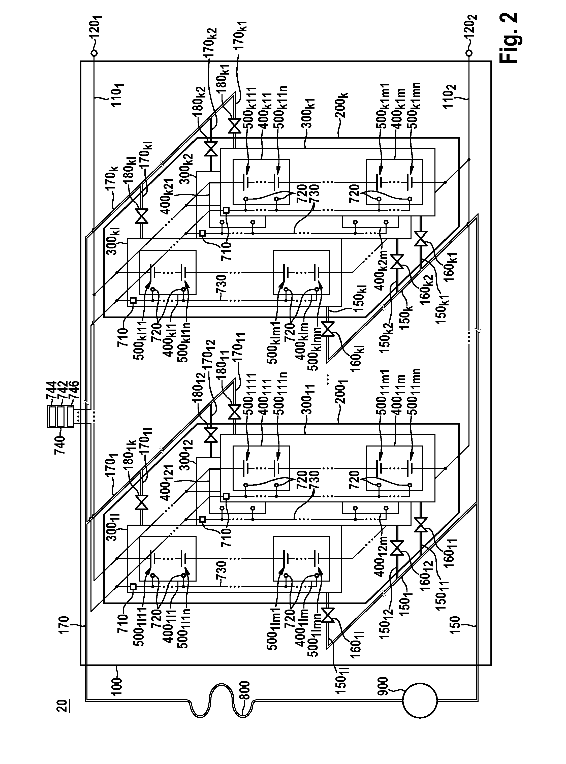
[0038]FIG. 2 shows a schematic view of an energy store 20 according to one embodiment of the invention.

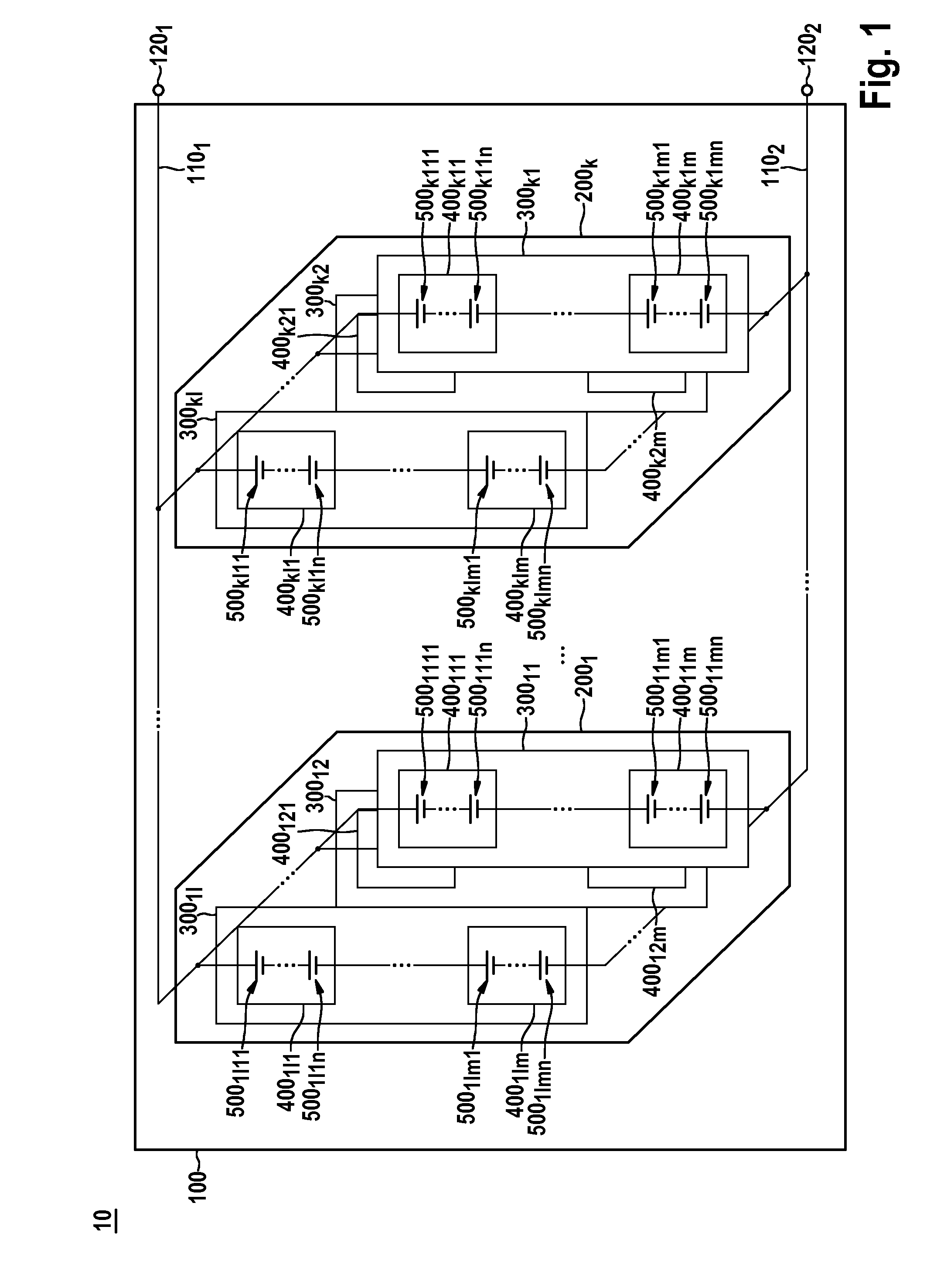
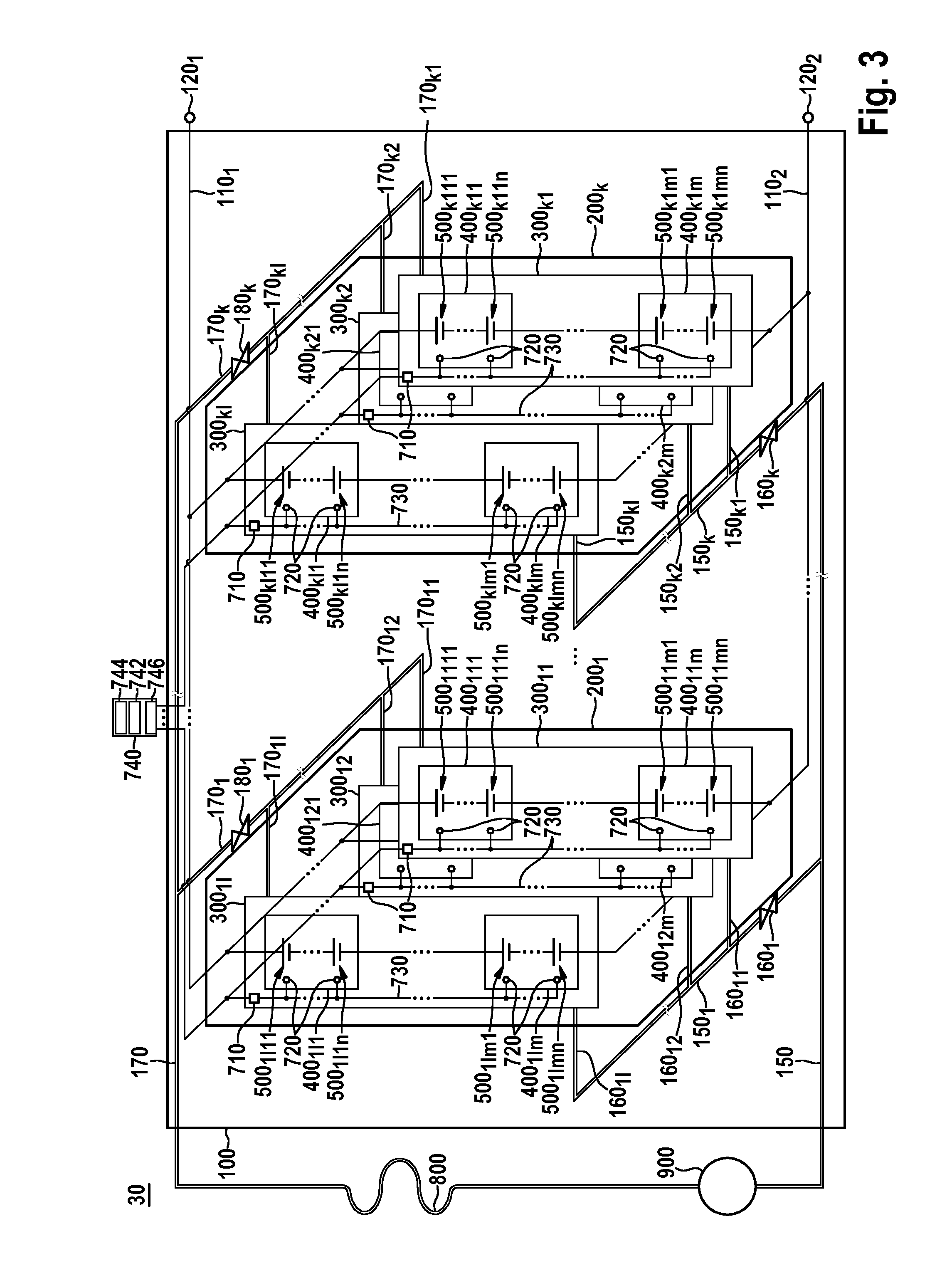
[0039]The energy store or respectively the battery system comprises a plurality of battery cells 5001111 to 500klmn. Each battery cell can, for example, have a voltage of 4.5 V and a capacity of 60-75 Ah. The plurality of battery cells 5001111 to 500klmn is arranged in a plurality of battery modules 400111 to 400klmn, so that each battery module comprises n battery cells. Each battery module can, for example, comprise n=11 to 13 battery cells that are connected in series and therefore have a voltage of 50-60 V and a capacity of 60-75 Ah. The plurality of battery modules 400111 to 400klm is arranged in a plurality of battery strings 30011 to 300kl, so that each battery string comprises m battery modules. Each battery string can, for example, comprise m=13 to 20 battery modules which are connected in series and thus have a voltage of 640-1170 V and a capacity of 60-75 Ah. The plurali...


PUM


Abstract

The invention relates to a device (710, 720, 730, 740) for monitoring an energy store (20; 30) comprising a plurality of battery cells (5001111-500klmn), which are arranged in a plurality of battery groups (2001-200k, 30011-300kl, 400111-400klm), and a temperature-control device for controlling the temperature of the battery cells (5001111-500klmn) by means of a plurality of partial flows of a temperature-control medium, each of the partial flows being associated with one of the battery groups (2001-200k, 30011-300kl, 400111-400klmn), characterized by: a plurality of sensor apparatuses (720) for sensing temperature measurement values of the battery cells (5001111-500klmn), each of the sensor apparatuses (720) being arranged in such a way that the sensor apparatus can sense the temperature measurement value of one of the battery cells (5001111-500klmn); an apparatus (710, 740) for determining a plurality of average temperature values from the sensed temperature measurement values, each of the determined average temperature values being determined in such a way that the determined average temperature value is associated with one of the battery groups (2001-200k, 30011-300kl, 400111-400klmn); and an apparatus (740) for evaluating the plurality of determined average temperature values and, if one of the determined average temperature values exceeds a temperature threshold value, determining that the partial flow associated with the associated battery group (2001-200k, 30011-300kl, 400111-400klm) has a fault. The invention further relates to a battery system, a vehicle, a method, a computer program, and a computer program product.

Description

BACKGROUND OF THE INVENTION[0001]The invention relates to a device and method for monitoring an energy store or respectively battery system as well as to an energy store having the device. The invention further relates to a vehicle, in particular a motor vehicle such as an electric vehicle or hybrid vehicle having the energy store.[0002]It is foreseeable that new battery systems, for example comprising lithium-ion batteries or nickel-metal hydride batteries, will increasingly be used in stationary applications, for example in wind turbines, in industry or in domestic engineering as well as in mobile applications, for example in electric vehicles (EV) or hybrid vehicles (hybrid electric vehicles HEV) as rechargeable energy stores.[0003]The battery systems have to meet very high requirements with regard to available energy content, charging and discharging efficiency, reliability, service life and with regard to undesirable loss of capacity due to frequent partial discharge.[0004]A ba...

Claims


Application Information

Patent Timeline
IPC IPC(8): H01M10/633B60L11/18H01M10/6568H01M10/48H01M10/625
CPCH01M10/633H01M10/486H01M10/482H01M10/625B60L2200/32B60L11/1874H01M2220/20B60L2200/10B60L2200/12H01M10/6568H01M10/6556H01M10/6567H01M10/617Y02B10/30B60L58/26Y02T10/70Y02E60/10
Inventor ESTEGHLAL, GHOLAMABAS
Owner ROBERT BOSCH GMBH
Why Eureka
Try Eureka