
Exhaust purification system for internal combustion engine

Inactive Publication Date: 2016-11-03
TOYOTA JIDOSHA KK
View PDF2 Cites 2 Cited by
  • Summary
  • Abstract
  • Description
  • Claims
  • Application Information

AI Technical Summary

Benefits of technology

The patent text describes a way to prevent damage caused by heat while also reducing the generation of NOx. This means that we can control the pollutant that causes a lot of harm to the environment.

Problems solved by technology

For this reason, when ending rich control, if immediately resetting the amount of the exhaust recirculation gas from the high pressure exhaust gas recirculation passage, a large amount of high temperature exhaust gas will flow into the high pressure exhaust gas recirculation passage and the high pressure exhaust gas recirculation passage or high pressure exhaust gas recirculation control valve will be liable to be damaged by the heat.
However, if the exhaust gas recirculation rate is held low, production of NOX might not be able to be reduced.
Further, a temperature of the exhaust recirculation gas supplied from the low pressure exhaust gas recirculation passage is relatively low.

Method used


Image

  • Exhaust purification system for internal combustion engine
  • Exhaust purification system for internal combustion engine
  • Exhaust purification system for internal combustion engine

Examples


Embodiment Construction

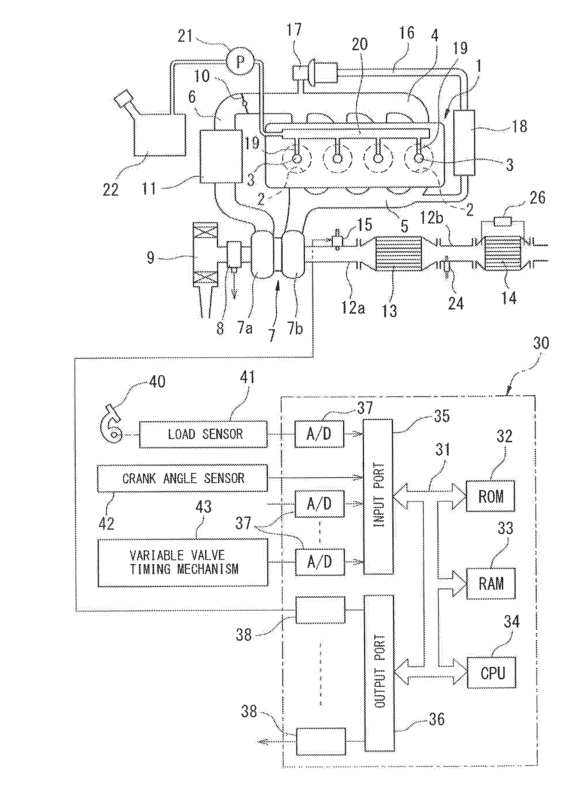
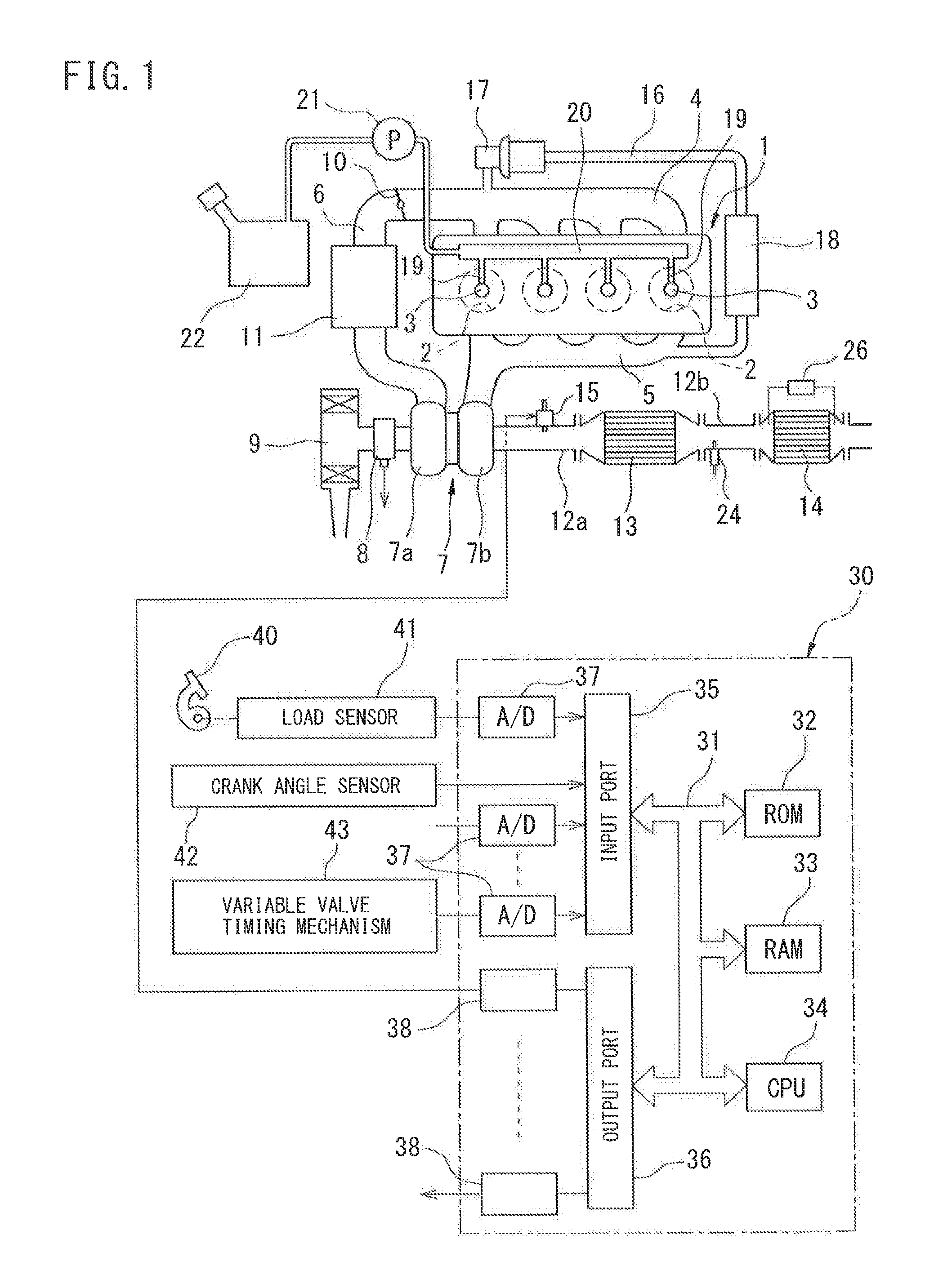
[0031]FIG. 1 is an overall view of a compression ignition type internal combustion engine. Referring to FIG. 1, 1 indicates an engine body, 2 a combustion chamber of each cylinder, 3 an electronically controlled fuel injector for injecting fuel into each combustion chamber 2, 4 an intake manifold, and 5 an exhaust manifold. The intake manifold 4 is connected through an intake duct 6 to an outlet of a compressor 7a of an exhaust turbocharger 7, while an inlet of the compressor 7a is connected through an intake air amount detector 8 to an air cleaner 9. Inside the intake duct 6, a throttle valve 10 driven by an actuator is arranged. Around the intake duct 6, a cooling device 11 is arranged for cooling an intake air flowing through the inside of the intake duct 6. In the embodiment shown in FIG. 1, an engine cooling water is guided to the inside of the cooling device 11 where the engine cooling water is used to cool the intake air.

[0032]On the other hand, the exhaust manifold 5 is conn...


PUM


Abstract

Rich control is performed to hold an air-fuel ratio of an exhaust gas discharged from an engine combustion chamber temporarily richer than the stoichiometric air-fuel ratio by injecting additional fuel into a cylinder in an expansion stroke or exhaust stroke while an exhaust gas recirculation rate is made lower than a base exhaust gas recirculation rate. A variable valve timing mechanism able to change an overlap period is provided. When ending rich control (ta2), the injection of additional fuel is stopped and the overlap period (OL) is increased from a base overlap period (OLB) and held there while an EGR rate (REGR) is kept lower than a base EGR rate (REGRB) and when a delay time (dt) elapses, the EGR rate and the overlap period are reset to the base EGR rate and the base overlap period.

Description

CROSS-REFERENCE TO RELATED APPLICATIONS[0001]This application is a national phase application of International Application No. PCT / JP2013 / 084371, filed Dec. 20, 2013, the content of which is incorporated herein by reference.TECHNICAL FIELD[0002]The present invention relates to an exhaust purification system for an internal combustion engine.BACKGROUND ART[0003]An exhaust purification system for an internal combustion engine is known in the art, where an exhaust turbocharger is provided for driving a compressor arranged in an engine intake passage upstream of a throttle valve using an exhaust turbine arranged inside an engine exhaust passage, the engine exhaust passage upstream of the exhaust turbine and the engine intake passage downstream of the throttle valve are connected by a high pressure exhaust gas recirculation passage while a high pressure exhaust gas recirculation control valve is arranged in the high pressure exhaust gas recirculation passage, the engine exhaust passage d...

Claims


Application Information

Patent Timeline
IPC IPC(8): F02D41/02F02M26/05F02D41/14F02D41/40F02D13/02F02D41/00
CPCF02D41/0275F02D13/0261F02M26/05F02D41/1461F02D41/405F02D41/0055F01N3/0842F01N3/0871F01N2560/06F01N2610/03F01N2900/0416F01N2900/1602F01N2900/1614F02D13/0219F02D13/0249F02D41/006F02D41/1462F02D2041/001F02D2200/0811Y02T10/12Y02T10/40
Inventor NOGI, YOSHITO
Owner TOYOTA JIDOSHA KK
Learn More