Temperature probe thermowell assembly

a technology of thermowell and thermowell assembly, which is applied in the direction of temperature measurement of flowing materials, instruments, heat measurement, etc., can solve the problems of excessive air gaps between slide-in temperature sensors, inability to overlook the disadvantages of slide-in temperature sensors, and insufficient tubing size of thermowells and sensors, etc., to reduce thermal mass and conductivity, reduce thermal lag, and enhance functionality

Inactive Publication Date: 2016-11-03
US THERMOAMP
View PDF6 Cites 6 Cited by
  • Summary
  • Abstract
  • Description
  • Claims
  • Application Information

AI Technical Summary

Benefits of technology

[0013]Generally, provided is a temperature probe thermowell assembly that minimizes thermal lag by having a reduced thermal mass and conductivity and that is useful in connection with both new and existing heat exchange systems and arrangements. In various preferred and non-limiting embodiments, provided are different configurations of a temperature probe thermowell assembly having enhanced functionality, reduced air gaps, reduced thermal mass, reduced epoxy volume, fast response time, and / or enhanced manufacturing.
[0014]According to one non-limiting embodiment or aspect of the present disclosure, a temperature probe assembly is provided that can be used to replace a slide-in temperature sensor and thermowell with a combination probe thermowell of the same size, which is capable of using the same sealing gland and which greatly reduces response time by reducing the thermal mass of the probe assembly. The tube housing is separated from the probe to allow for the minimization of both the probe housing mass and the probe epoxy mass required to embed the thermistor by using bare wire / thermistor leads separated by very thin insulating paper to prevent shorting while allowing epoxy penetration. A snap ring, or alternatively a set of special threads, are used in combination with an O-ring sealing gland to allow for quick assembly and sealing.
[0015]According to another non-limiting embodiment or aspect of the disclosure, a three piece temperature probe assembly is provided that includes a small probe fitting that maintains the same overall diameter as a typical slide-in probe. The fitting houses the thermistor, epoxy, cabling, etc. in its interior in a manner that minimizes epoxy use and maximizes thermal exposure to the fluid. Using a very thin insulating paper, which is approximately 0.003″ thick, wrapped between and around the thermistor wire leads prior to injection of the sealing epoxy allows for minimal epoxy volume while still ensuring that no shorting or electrical conduction occurs between the wires, solder, etc. A sealing O-ring gland and a fastening feature using a snap ring or a special reduced pitch thread are provided on the exterior of the fitting to allow easy and quick assembly of the fitting to the remainder of the assembly. The assembly also includes a weld socket fitting with one end designed to be welded to the thermowell tube to seal out fluid at one end and to lock in and seal the probe fitting at the other end using either the snap ring or threaded feature and O-ring sealing gland. The assembly further includes a short piece of thin wall tubing which can be welded to the weld socket fitting.

Problems solved by technology

It is noted that standard tubing sizes for thermowells and sensors are not designed to fit inside each other.
However, there are disadvantages associated with using slide-in temperature sensors that cannot be overlooked.
During operation, slide-in temperature sensors may have excessive air gaps between the sensor and the thermowell.
In addition, most slide-in temperature sensors create a high thermal mass because its housing tube must be filled and sealed with epoxy.
All of these factors make it difficult to obtain a fast response time when the fluid is heating up so as not to overshoot the set temperature.
The thermal lag will result in inaccurate temperature readings and cycling of the heating or cooling device.

Method used


Image

  • Temperature probe thermowell assembly
  • Temperature probe thermowell assembly
  • Temperature probe thermowell assembly

Examples


Embodiment Construction

[0051]For purposes of the description hereinafter, special orientation terms, such as “end”, “upper”, “lower”, “right”, “left”, “vertical”, “horizontal”, “top”, “bottom”, “lateral”, “longitudinal”, and derivatives thereof, shall relate to the invention as it is oriented in the drawing figures. However, it is to be understood that the invention may assume various alternative variations and step sequences, except where expressly specified to the contrary. It is also to be understood that the specific devices and processes illustrated in the attached drawings, and described in the following specification, are simply exemplary embodiments or aspects of the invention. Hence, specific dimensions and other physical characteristics related to the embodiments or aspects disclosed herein are not to be considered as limiting.

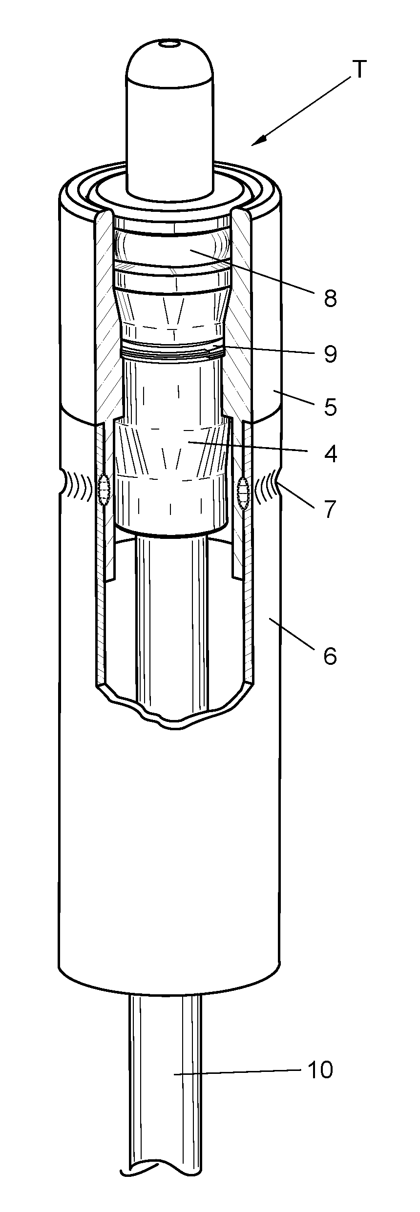
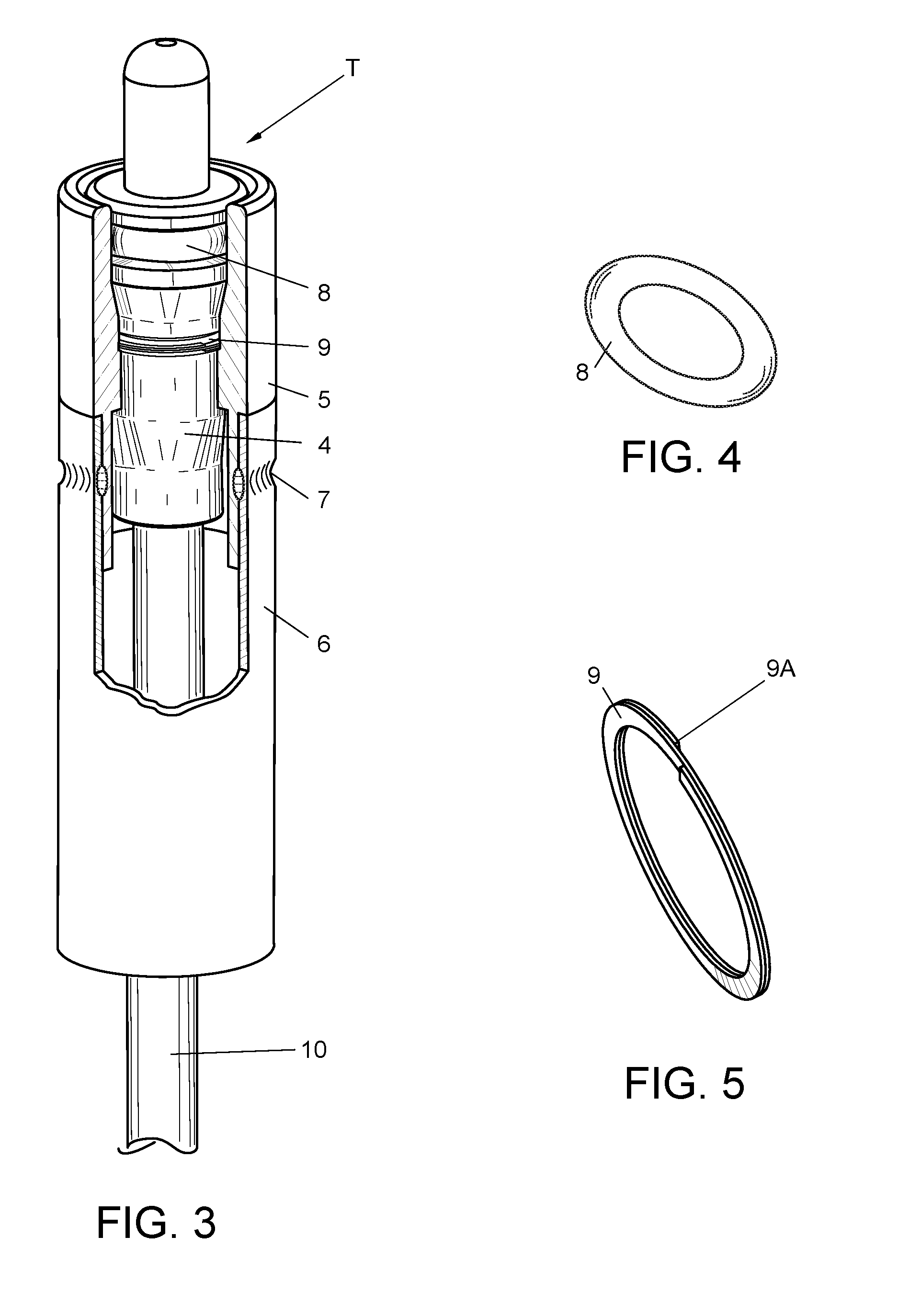
[0052]With reference to FIGS. 3-11, a temperature probe assembly T, according to a preferred and non-limiting embodiment or aspect of the present disclosure is shown. The ...


PUM

PropertyMeasurementUnit
temperatureaaaaaaaaaa
corrosionaaaaaaaaaa

Abstract

A temperature probe assembly includes an internal fitting having an exterior and a hollow interior; a temperature sensor disposed within the hollow interior of the internal fitting, the temperature sensor being configured to be placed in communication with an external controller; an external fitting disposed on the exterior of the internal fitting; and a tube connected to the external fitting. The temperature probe assembly is configured to be inserted into a thermowell. The tube and external fitting are configured to house and support the internal fitting in the thermowell.

Description

CROSS REFERENCE TO RELATED APPLICATION[0001]The present application claims priority from U.S. Provisional Patent Application No. 62 / 154,162, filed on Apr. 29, 2015, which is incorporated herein by reference in its entirety.BACKGROUND OF THE INVENTION[0002]1. Field of the Invention[0003]The present disclosure relates generally to fluid heating and / or cooling devices, such as air-source heat pumps, that use an electronic temperature probe in conjunction with a thermowell, and, in particular, to an improved thermowell assembly for a slide-in electronic temperature probe.[0004]2. Description of Related Art[0005]Heat pumps are increasingly replacing fossil fuel heaters, especially in applications where using a heat pump is a more cost-effective heating method. Air-source heat pumps have been used in various applications to transfer heat from outdoor air into another fluid or heat sink. Applications for such heat pumps include space and water heating, as well as providing process heat for...

Claims


Application Information

Patent Timeline
Patent Type & Authority Applications(United States)
IPC IPC(8): G01K1/08G01K13/02G01K7/22G01K1/14
CPCG01K1/08G01K7/22G01K13/02G01K1/14
Inventor BERNARDI, WILLIAM P.
Owner US THERMOAMP
Why Eureka
Try Eureka