Battery device

Active Publication Date: 2016-11-03
ABLIC INC
View PDF6 Cites 5 Cited by
  • Summary
  • Abstract
  • Description
  • Claims
  • Application Information

AI Technical Summary

Benefits of technology

[0015]A first charge/discharge control device is configured to monitor a charge/discharge current with a voltage generated across both ends of a charge/discharge control switch, and a second charge/discharge control device is configured to monitor the charge/discharge current with a voltage generated across both ends of a current sensing resistor. A field effect transistor forming the charge/discharge control switch is selected based on a desired ON resistance value. The charge/discharge control switch of the first charge/discharge control device includes a field effect transistor having the desired ON resistance value, and a charge/discharge control switch of the second charge/discharge control device includes a field effect transistor having an ON resistance value other than the desired ON resistance value.
[0016]According to the ba

Problems solved by technology

However, when an overcurrent detection function with good detection accuracy is to be realized in the related art as illustrated in FIG. 4, the following problem arises.
Thus, there is a problem i

Method used


Image

  • Battery device
  • Battery device
  • Battery device

Examples


Example

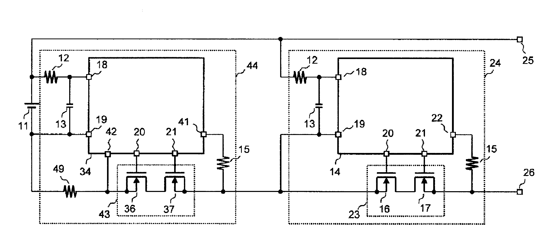
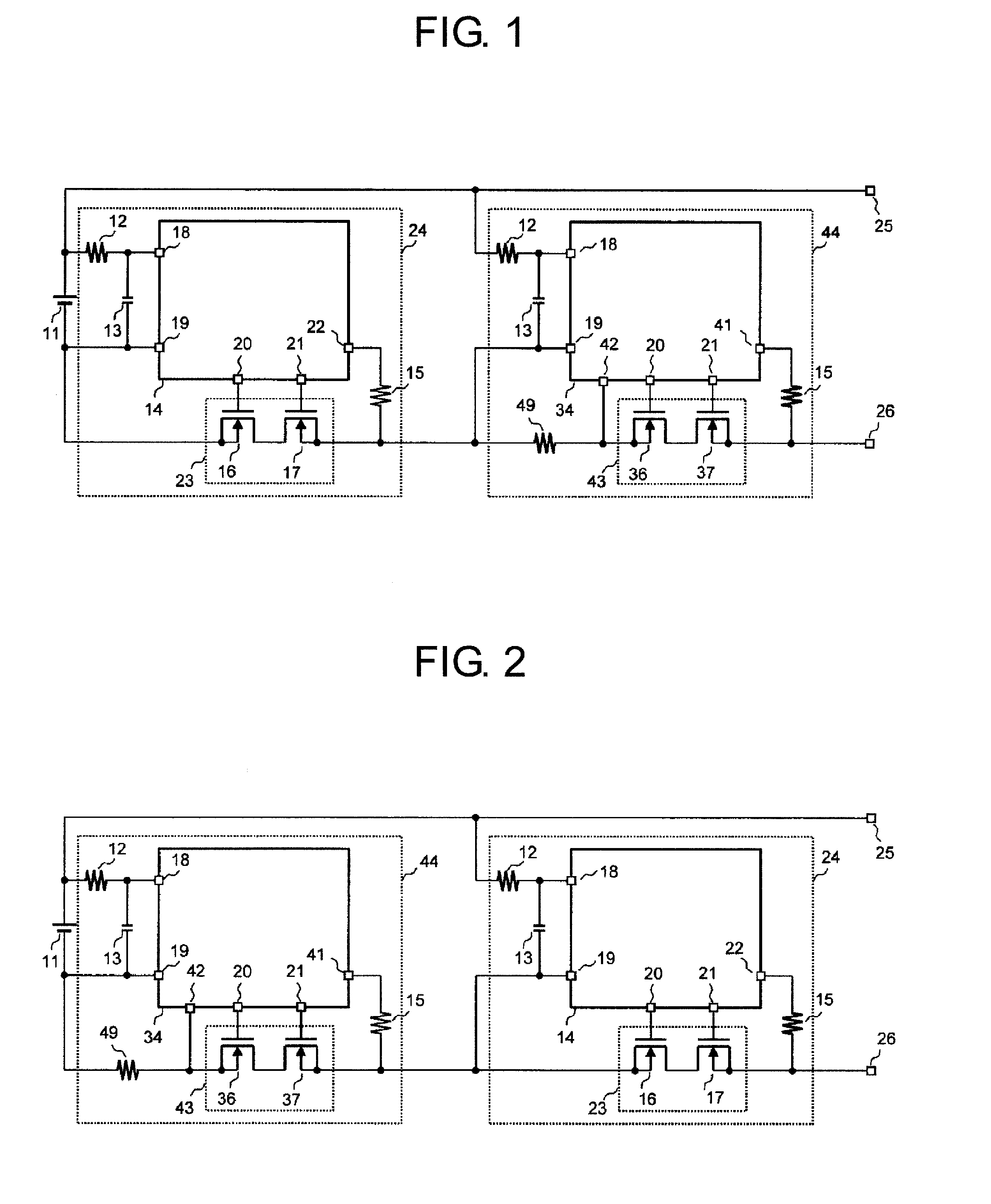
[0021]FIG. 1 is a circuit diagram of a battery device according to an embodiment of the present invention.

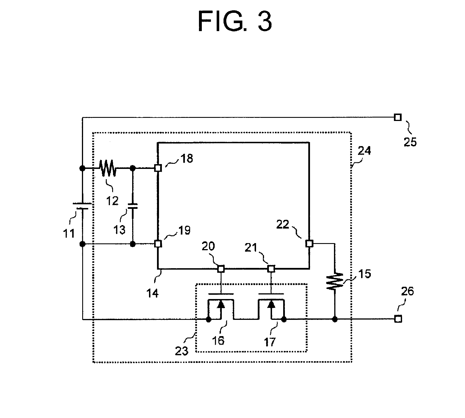
[0022]The battery device according to this embodiment includes a secondary battery 11, a first charge / discharge control device 24, a second charge / discharge control device 44, an external positive terminal 25, and an external negative terminal 26.

[0023]The first charge / discharge control device 24 includes a charge / discharge control circuit 14, a charge / discharge control switch 23, resistors 12 and 15, and a capacitor 13. The charge / discharge control switch 23 includes an Nch discharge control field effect transistor 16, and an Nch charge control field effect transistor 17. The charge / discharge control circuit 14 includes a positive power supply terminal 18, a negative power supply terminal 19, a discharge control signal output terminal 20, a charge control signal output terminal 21, and an overcurrent detection terminal 22.

[0024]The second charge / discharge control device 44 incl...


PUM


Abstract

Provided is a battery device having high overcurrent detection current accuracy that suppresses increases in a resistance value of a charge/discharge path and in a manufacturing cost. A first charge/discharge control device is configured to monitor a charge/discharge current with a voltage generated across both ends of a charge/discharge control switch, and a second charge/discharge control device is configured to monitor the charge/discharge current with a voltage generated across both ends of a current sensing resistor. A field effect transistor forming the charge/discharge control switch is selected based on a desired ON resistance value. The charge/discharge control switch of the first charge/discharge control device includes a field effect transistor having the desired ON resistance value, and a charge/discharge control switch of the second charge/discharge control device includes a field effect transistor having an ON resistance value other than the desired ON resistance value.

Description

RELATED APPLICATIONS[0001]This application claims priority under 35 U.S.C. §119 to Japanese Patent Application No. 2015-093262 filed on Apr. 30, 2015, the entire content of which is hereby incorporated by reference.BACKGROUND OF THE INVENTION[0002]1. Field of the Invention[0003]The present invention relates to a battery device including a charge / discharge control device configured to control the charging and discharging of a secondary battery.[0004]2. Description of the Related Art[0005]A battery device of the related art is illustrated in a circuit diagram of FIG. 3.[0006]The battery device of the related art includes a secondary battery 11, a charge / discharge control device 24, an external positive terminal 25, and an external negative terminal 26. The charge / discharge control device 24 includes a charge / discharge control circuit 14, resistors 12 and 15, a capacitor 13, and an N-channel (Nch) charge / discharge control switch 23. The charge / discharge control circuit 14 includes a po...

Claims


Application Information

Patent Timeline
IPC IPC(8): H02J7/00
CPCH02J7/0029H02J2007/0039H02J7/0077H02J7/0068H02J7/0047H02J7/00304H02J7/0031Y02E60/10G01R31/3842G01R1/203G01R19/16542G01R19/16571H01M10/44H01M10/48H02J7/007
Inventor MAETANI, FUMIHIKO
Owner ABLIC INC
Why Eureka
Try Eureka