Resonant step-down dc-dc power converters

Active Publication Date: 2016-11-03
DANMARKS TEKNISKE UNIV
View PDF9 Cites 22 Cited by
  • Summary
  • Abstract
  • Description
  • Claims
  • Application Information

AI Technical Summary

Benefits of technology

[0011]Furthermore, the reduced amount of power which needs to be transferred through the resonant step-down DC-DC converter leads to reduced power handling requirements for both passive and active components, e.g. semiconductors switches, capacitors, diodes etc., allowing less costly and physically smaller components to be applied. A yet further significant advantage of the present resonant step-down DC-DC converter is that the primary side circuit is only subjected to the input voltage between the positive and negative input terminals of the primary side circuit instead of the entire converter input voltage supplied by the external input voltage or power source as in ordinary isolated DC-DC power converters. As described above, the input voltage or power source is connected either between the negative input terminal and the positive electrode of the output capacitor or, in the second case, between the negative electrode of the output capacitor and the positive input terminal of the primary side circuit in the present resonant step-down DC-DC converter. The reduced voltage levels in the primary side circuit of the resonant step-down DC-DC power converter reduce the required maximum voltage ratings of active and passive components therein such as semiconductor switch or switches, inductor(s), capacitors, diode(s) etc. The reduced maximum voltage rating leads to physically smaller and/or less costly active and passive components with increased life span.
[0012]The galvanic isolation barrier may comprise a transformer which comprises a pair of electro-magnetically or magnetically coupled inductors comprising a first inductor electrically connected to the primary side circuit and a second inductor electrically connected to the secondary side circuit. The first and second inductors could be discrete windings both wound around a common magnetic permeable structure to form an isolation transformer. In one alternative embodiment, the first and second inductors are arranged to be electro-magnetically coupled without a common magnetically permeable structure to form a coreless isolation transformer. In such a coreless isolation transformer, the first and second inductors may be integrated in a printed circuit board without intervening magnetic material. The printed circuit board could have the entire resonant step-down DC-DC power converter mounted thereon. The first and second inductors are preferably arranged such that a magnetic coupling factor, k, between the first and second inductors is larger than 0.25. The first and second inductors of the coreless isolation transformer may for example comprise first and second embedded coils, respectively, formed in one or more conductive layers of the printed circuit board as disclosed in the applicant's co-pending application No. PCT/EP2014/079037.
[0013]In yet another embodiment, the galvanic isolation barrier comprises a first capacitor coupled in series with the positive input terminal of the primary side circuit and the first positive electrode of the output capacitor and a second capacitor coupled in series with the negative input terminal of the primary side circuit and the second negative e

Problems solved by technology

Resonant power converters are particularly useful for high switching frequencies such as frequencies above 1 MHz where switching losses of standard SMPS topologies (Buck, Boost etc.) tend to be un

Method used


Image

  • Resonant step-down dc-dc power converters
  • Resonant step-down dc-dc power converters
  • Resonant step-down dc-dc power converters

Examples


Embodiment Construction

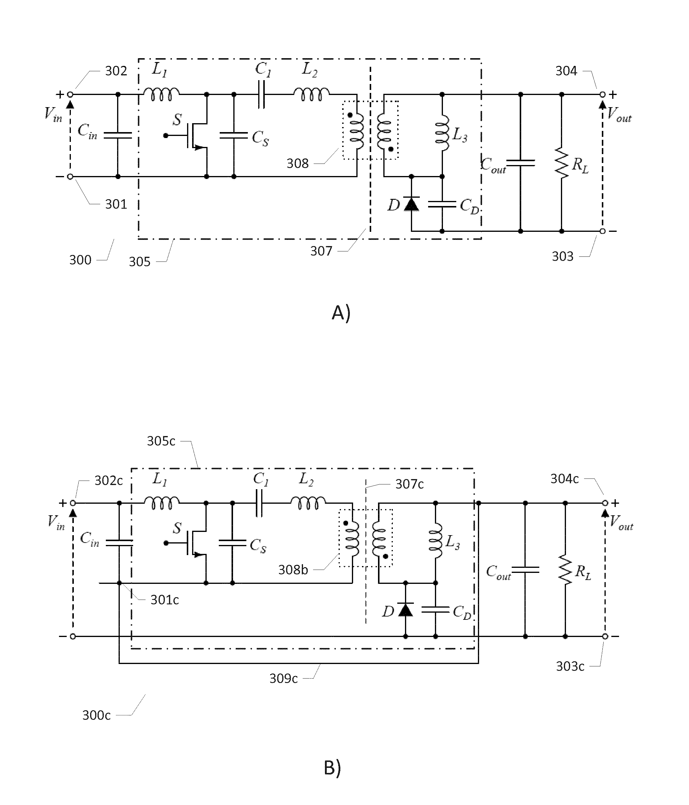
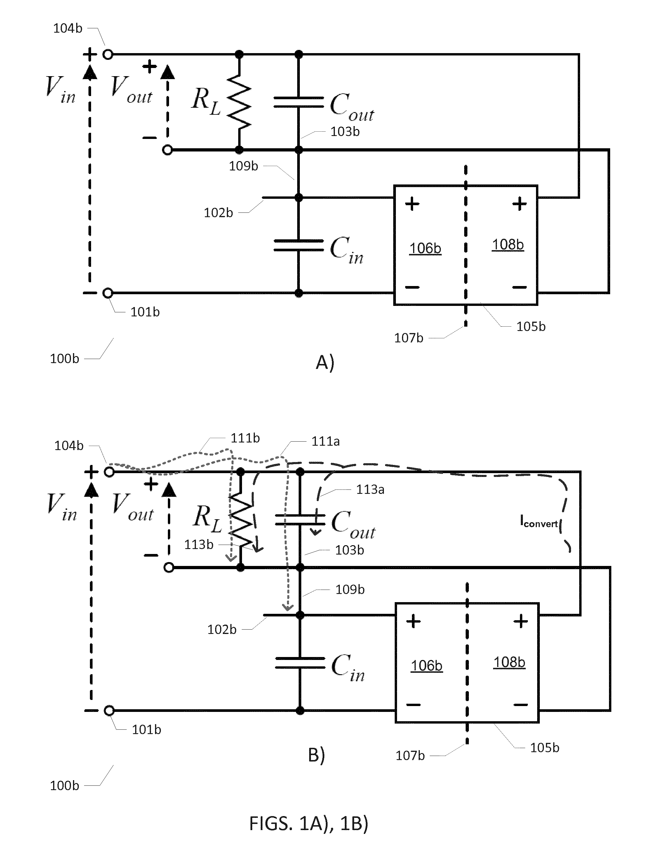
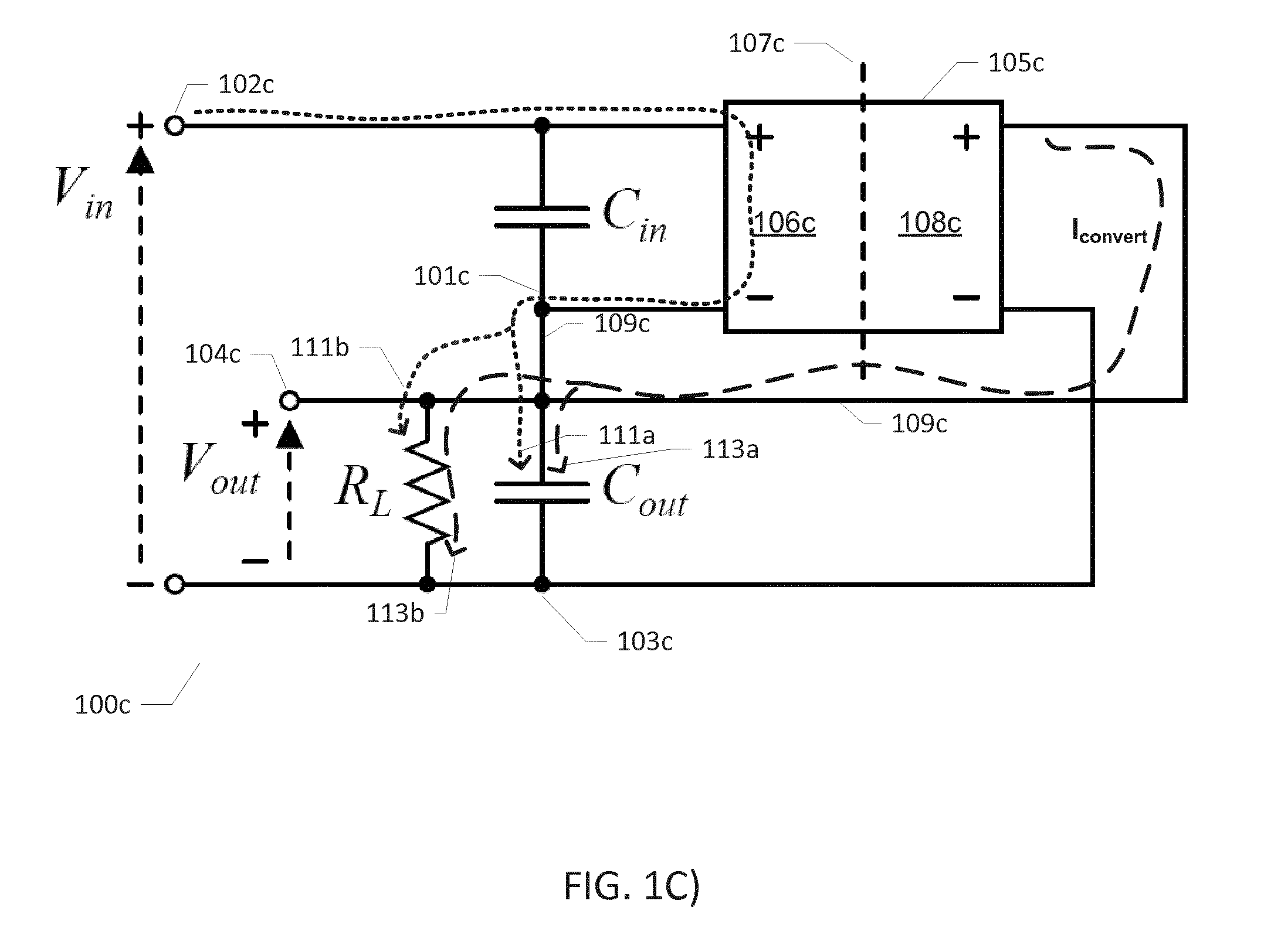
[0043]FIGS. 1A), 1B) and 1C) are simplified electrical circuit diagrams 100a, 100b, 100c illustrating basic operational features of two different embodiments of resonant step-down DC-DC power converters in accordance with the present invention. The first embodiment is illustrated on FIGS. 1A) and 1B) while the second embodiment is illustrated on FIG. 1C).

[0044]FIG. 1A) shows a resonant step-down DC-DC power converter 100b comprising a primary side circuit and a secondary side circuit connected through a galvanic isolation barrier 107b. The primary side circuit comprises a positive input terminal 102b and a negative input terminal 101b for receipt of a DC or AC input voltage Vin from an input voltage or power source (not shown). An input capacitor Cin is electrically connected between the positive input terminal 102b and a negative input terminal 101b to form an energy reservoir for the input power or input voltage source. The primary side circuit additionally comprises an input side...


PUM


Abstract

The present invention relates to a resonant step-down DC-DC power converter which comprises a primary side circuit and a secondary side circuit coupled through a galvanic isolation barrier. The primary side circuit comprises a positive and a negative input terminal for receipt of an input voltage and an input capacitor coupled between the positive and negative input terminals and the secondary side circuit comprises an output capacitor chargeable to a converter output voltage between a first positive electrode and a second negative electrode. A resonant network is con-figured for alternatingly being charged from the input voltage and discharged to the output capacitor through the galvanic isolation barrier by a semiconductor switch arrangement in accordance with a switch control signal to produce the converter output voltage. The resonant step-down DC-DC power converter comprises an electrical short-circuit connection across the galvanic isolation barrier connecting, in a first case, the second negative electrode of the output capacitor to the positive input terminal of the primary side circuit or, in a second case, connecting the second positive electrode of the output capacitor to the negative input terminal of the primary side circuit thereby establishing in both the first and second cases a series coupling of the output capacitor and the input capacitor. A load connection is established, in the first case, between the first positive electrode of the output capacitor and the positive input terminal or, in the second case, between the second negative electrode of the output capacitor and the negative input terminal.

Description

[0001]The present invention relates to a resonant step-down DC-DC power converter which comprises a primary side circuit and a secondary side circuit coupled through a galvanic isolation barrier. The primary side circuit comprises a positive and a negative input terminal for receipt of an input voltage and an input capacitor coupled between the positive and negative input terminals and the secondary side circuit comprises an output capacitor chargeable to a converter output voltage between a first positive electrode and a second negative electrode. A resonant network is configured for alternatingly being charged from the input voltage and discharged to the output capacitor through the galvanic isolation barrier by a semiconductor switch arrangement in accordance with a switch control signal to produce the converter output voltage. The resonant step-down DC-DC power converter comprises an electrical short-circuit connection across the galvanic isolation barrier connecting, in a first...

Claims


Application Information

Patent Timeline
IPC IPC(8): H02M3/335H02M1/42H05B33/08H02M1/08H02M1/00H05B44/00
CPCH02M3/33523H05B33/0815H02M1/4241H02M1/08H02M3/33576H05B45/382H05B45/3725H05B45/39H02M1/0058Y02B70/10
Inventor KOVACEVIC, MILOVANMADSEN, MICKEY P.
Owner DANMARKS TEKNISKE UNIV
Why Eureka
Try Eureka