Colour Measurement Method and Colour Measurement Device

a technology of colour measurement and measurement method, applied in the direction of optical radiation measurement, instruments, spectrometry/spectrophotometry/monochromators, etc., can solve the problems of measurement error when using such colour measurement device, requiring more apparatus and/or complex measurement device, and being relatively elaborate in purely procedural terms. , to achieve the effect of simple correction of the distortion of measurement values

Active Publication Date: 2016-11-10
X RITE SWITZERLAND
View PDF3 Cites 8 Cited by
  • Summary
  • Abstract
  • Description
  • Claims
  • Application Information

AI Technical Summary

Benefits of technology

[0014]Calculating and applying a correction model, in accordance with the invention, allows a relatively simple correction of the distortions in the measurement values caused by angular errors, without changing the design of the colour measurement device used. The correction model can be uniformly used for all measurement geometries.

Problems solved by technology

In the publication “Device Profiling: Managing Global Colour Consistency” by Wilhelm H. Kettler, DFO Conference on Quality Assurance and Testing Methods 2008, different causes are presented which can lead to measurement errors when using such colour measurement devices.
These include in particular the so-called systematic errors which are due to certain deficiencies of the device, such as for example faulty calibration.
Angular errors, i.e. deviations between actual illumination and observation directions of the measurement device and corresponding nominal illumination and observation directions as predetermined by the measurement geometry selected, have a particularly significant effect, precisely when performing measurements on samples containing effect paints.
The measures described in these documents, however, require more apparatus and / or more complex measurement devices and are also relatively elaborate in purely procedural terms.

Method used


Image

  • Colour Measurement Method and Colour Measurement Device
  • Colour Measurement Method and Colour Measurement Device
  • Colour Measurement Method and Colour Measurement Device

Examples


Embodiment Construction

)

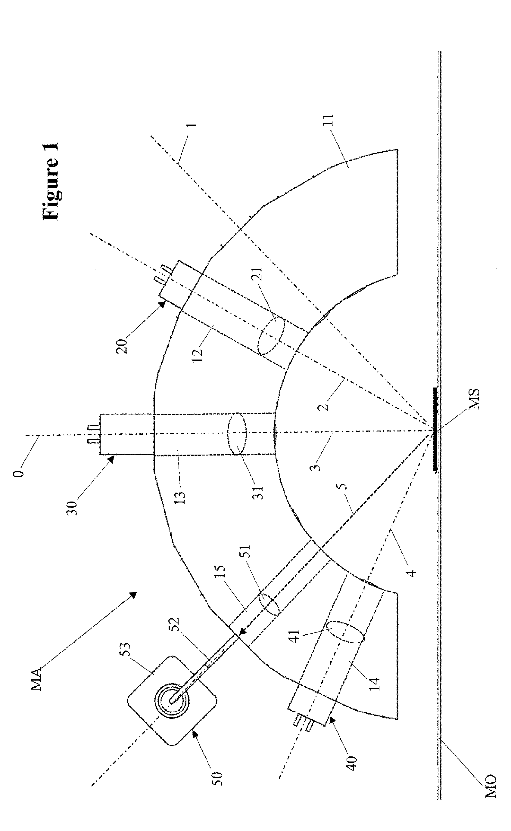
[0034]The following rule applies to the description of the figures below: wherever individual reference signs are not entered in a figure, reference is made in this respect to the other figures and the corresponding parts of the description. The term “measurement array” is understood to mean the sum of the components of the colour measurement device which serve to illuminate a measurement spot on the surface of a measurement object and to detect the light reflected by this measurement spot and convert it into corresponding electrical signals. The term “device normal” is to be understood to mean an (imaginary) line which is fixed relative to the device and (ideally) perpendicular to the surface of the measurement object when using the colour measurement device in practice, and which defines the centre point of the measurement spot. The term “actual illumination direction” is to be understood to mean the direction in which the measurement spot is illuminated. Similarly, the term “act...


PUM


Abstract

A colour measurement device includes a measurement array (MA) which includes: a plurality of illumination arrays (20, 30, 40) for exposing a measurement spot (MS) on a measurement object (MO) to illumination light in an actual illumination direction (2, 3, 4) in each case, and a pick-up array (50) for detecting the measurement light reflected by the measurement spot (MS) in an actual observation direction (5) and for converting it into preferably spectral reflection factors; and a controller for the illumination arrays and the pick-up array and for processing the electrical signals produced by the pick-up array. The controller is embodied to process the measured reflection factors on the basis of a correction model, such that distortions in the measurement values as compared to nominal illumination and / or observation directions, caused by angular errors in the illumination arrays and / or the pick-up array, are corrected.

Description

BACKGROUND[0001]1. Technical Field[0002]The present invention relates to colour measurement methods and to colour measurement devices.[0003]2. Background Art[0004]Colour measurement devices of the type under discussion can be embodied, irrespective of the underlying measurement technology, as autonomous devices or as peripheral measurement devices for use in connection with a controlling computer which evaluates measurement data. Autonomous colour measurement devices contain all the operating and display members necessary for measurement operations and also their own power supply and are in many cases also equipped with an interface for communicating with a computer, wherein both measurement data and control data can be exchanged with the computer. Colour measurement devices which are configured as peripheral measurement devices do not generally have their own operating and display members and are controlled by the superordinate computer like any other peripheral computer device. Fo...

Claims


Application Information

Patent Timeline
Patent Type & Authority Applications(United States)
IPC IPC(8): G01J3/02G01J3/46
CPCG01J3/46G01J3/0297G01J3/504G01J3/524
Inventor EHBETS, PETERLICHTENAUER, MATTHIAS SCHELLER
Owner X RITE SWITZERLAND
Why Eureka
Try Eureka