
Protective film for wavelength conversion sheet, wavelength conversion sheet and backlight unit

Inactive Publication Date: 2016-11-10
TOPPAN PRINTING CO LTD
View PDF17 Cites 13 Cited by
  • Summary
  • Abstract
  • Description
  • Claims
  • Application Information

AI Technical Summary

Benefits of technology

The present invention provides a protective film for wavelength conversion sheets that can effectively barrier for a long time, preventing insufficient barrier caused by splashes, scratches, wrinkles, and other factors. This protective film improves the quality and durability of the wavelength conversion sheet and backlight unit.

Problems solved by technology

However, the thus obtained white light is usually somewhat bluish and often gives the impression of “cold” or “coolish” white color.
Contrary to such a demand, the conventional barrier films pose a drawback of failing to achieve a satisfactory performance as most of them have been used as wrapping materials for food, pharmaceutical products and the like and packaging materials for electronic devices or the like.

Method used


Image

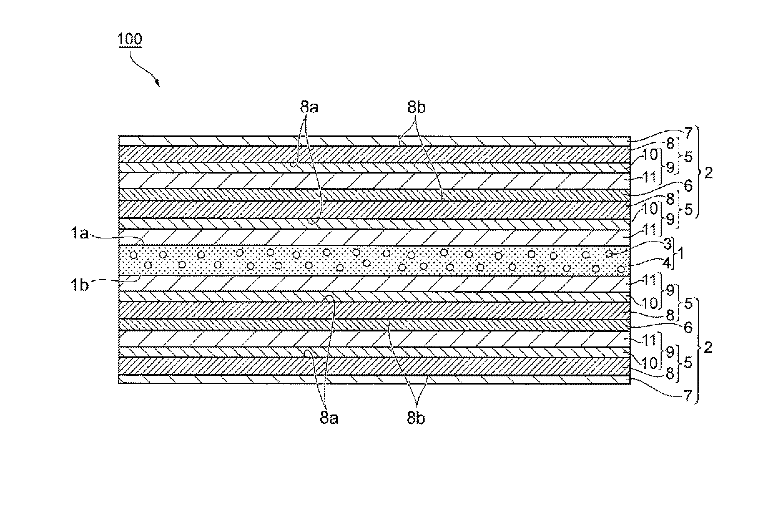
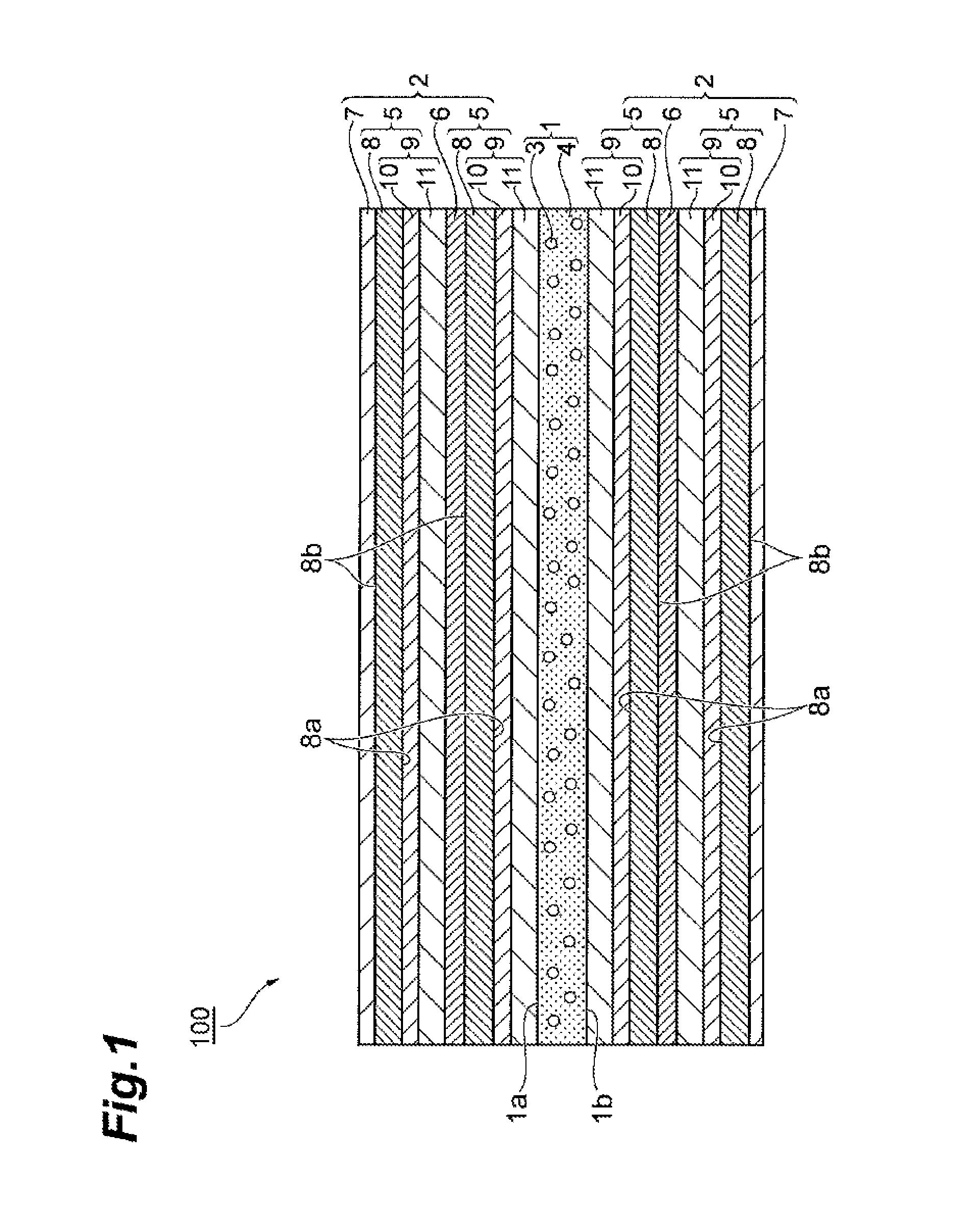
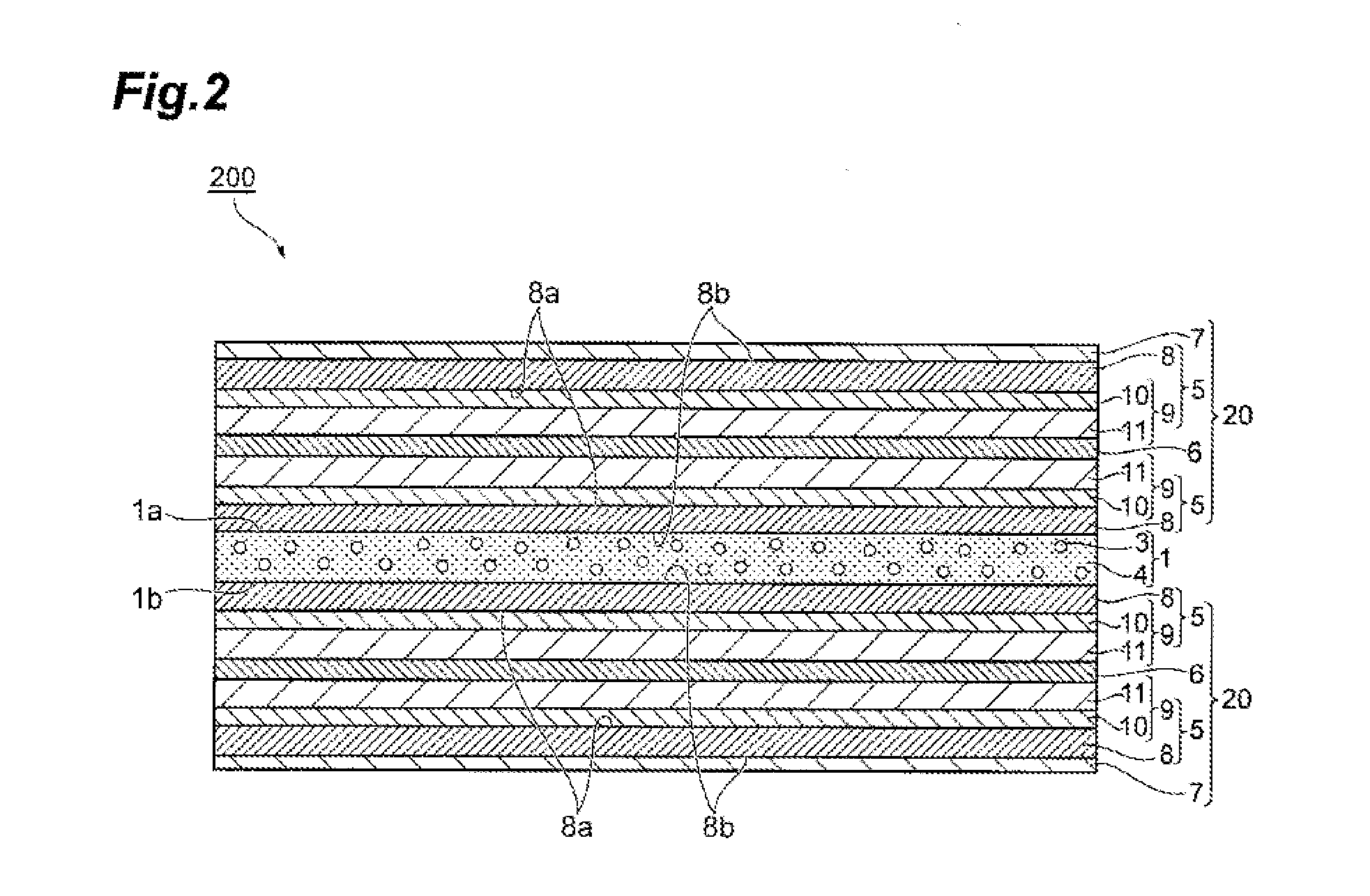
  • Protective film for wavelength conversion sheet, wavelength conversion sheet and backlight unit
  • Protective film for wavelength conversion sheet, wavelength conversion sheet and backlight unit
  • Protective film for wavelength conversion sheet, wavelength conversion sheet and backlight unit

Examples


example 1

Production of Protective Film for Wavelength Conversion Sheet

[0137]Silicon oxide, as the inorganic thin film layer (silica deposition layer) was provided to a thickness of 250 Å by the vacuum deposition method on one surface of a 25 μm-thickness polyethylene terephthalate film as a substrate, and a coating liquid containing tetraethoxysilane and polyvinyl alcohol was further applied onto the inorganic thin film layer by the wet coating method to form a 0.3 μm-thickness gas barrier covering layer. Thus, a barrier film, in which the barrier layer comprising the inorganic thin film layer and the gas barrier covering layer is provided on one surface of the substrate, was obtained. Two sheets of the thus obtained barrier film were produced.

[0138]Subsequently, a coating liquid containing an acrylic resin and silica microparticles (average particle size of 3 μm) was applied by the wet coating method onto the surface opposite side (substrate side) to the gas barrier covering layer of one of...

example 2

Production of Protective Film for Wavelength Conversion Sheet

[0144]A protective film for wavelength conversion sheet of Example 2 was obtained in the same manner as in Example 1, except that the side of the gas barrier covering layer of the barrier film provided with the coating layer is affixed, using an acrylic resin adhesive, with the side of the gas bather covering layer of the barrier film on which the coating layer was not formed. Two sheets of the thus obtained protective film for wavelength conversion sheet were produced.

[0145](Production of Wavelength Conversion Sheet)

[0146]CdSe / ZnS 530 (tradename, manufactured by SIGMA-ALDRICH Co. LLC) was mixed with an epoxy photosensitive resin, subsequently the mixed solution was applied onto the substrate side (the surface opposite side to the coating layer) of the protective film for wavelength conversion sheet described above, and a protective film for wavelength conversion sheet having the same configuration was laminated thereon to...

example 3

[0149]A protective film for wavelength conversion sheet of Example 3 was obtained in the same operation as in Example 1, except that the coating layer was not provided. Further, a wavelength conversion sheet and a backlight unit of Example 3 were obtained in the same operation as in Example 1, except that the obtained protective film for wavelength conversion sheet was used.


PUM

PropertyMeasurementUnit
Fractionaaaaaaaaaa
Fractionaaaaaaaaaa
Fractionaaaaaaaaaa

Abstract

A protective film for wavelength conversion sheet for protecting a fluorescent substance in a wavelength conversion sheet, the protective film for wavelength conversion sheet having a structure in which two or more barrier films, each comprising a substrate and one or more barrier layers provided on at least one surface of the substrate, are laminated.

Description

TECHNICAL FIELD[0001]The present invention relates to a protective film for wavelength conversion sheet, and a wavelength conversion sheet using the same and a backlight unit.BACKGROUND ART[0002]A liquid crystal display is a display apparatus for displaying images and the like by applying voltage to control the orientation of the liquid crystals and passing or blocking light in each area. A back light provided on the back of a liquid crystal display is used as a light source for the liquid crystal display. Although a cold cathode tube has conventionally been used as the back light, a LED (light emitting diode) has recently been used in place of the cold cathode tube for the reasons of long operating life, bright colors, and the like.[0003]In the LED used for the back light, the white LED technology plays a critically important role. The white LED technology commonly uses a method of exciting a cerium-doped YAG:Ce (yttrium / aluminum / garnet:cerium) down-conversion fluorescent substance...

Claims


Application Information

Patent Timeline
IPC IPC(8): G02B1/14F21V8/00B32B7/12F21V9/40
CPCG02B1/14B32B7/12G02B6/005B32B2457/202B32B2307/418B32B2307/416B32B2307/422B32B2307/7242B32B27/00B32B27/08B32B27/20B32B27/28B32B27/36B32B2255/10B32B2255/20B32B2264/02B32B2264/102B32B2264/12B32B2307/306B32B2307/412B32B2551/00B32B2571/00F21S2/00G02B6/0023C08J5/18G02B27/0025
Inventor TOKINOYA, OSAMUKITAHARA, TSUKASANISHIKAWA, TAKESHI
Owner TOPPAN PRINTING CO LTD
Learn More