

Switched reluctance motor starting methods
Patent Information
- Authority / Receiving Office
- US · United States
- Patent Type
- Applications(United States)
- Current Assignee / Owner
- VALEO AIR MANAGEMENT UK
- Publication Date
- 2016-11-10
- Estimated Expiration
- Not applicable · inactive patent
Smart Images
Figure 1 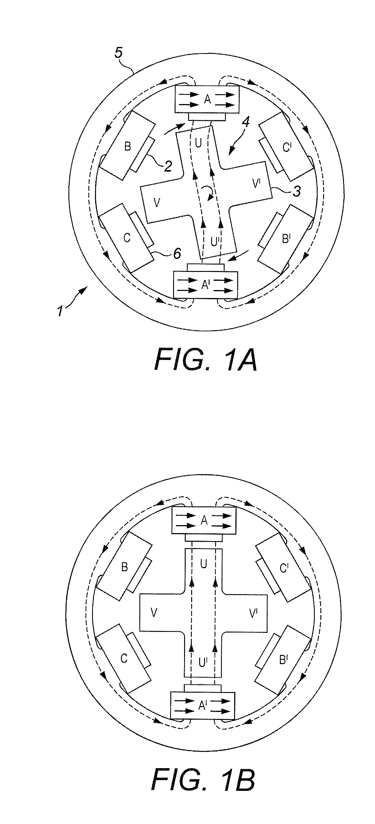
Figure 2 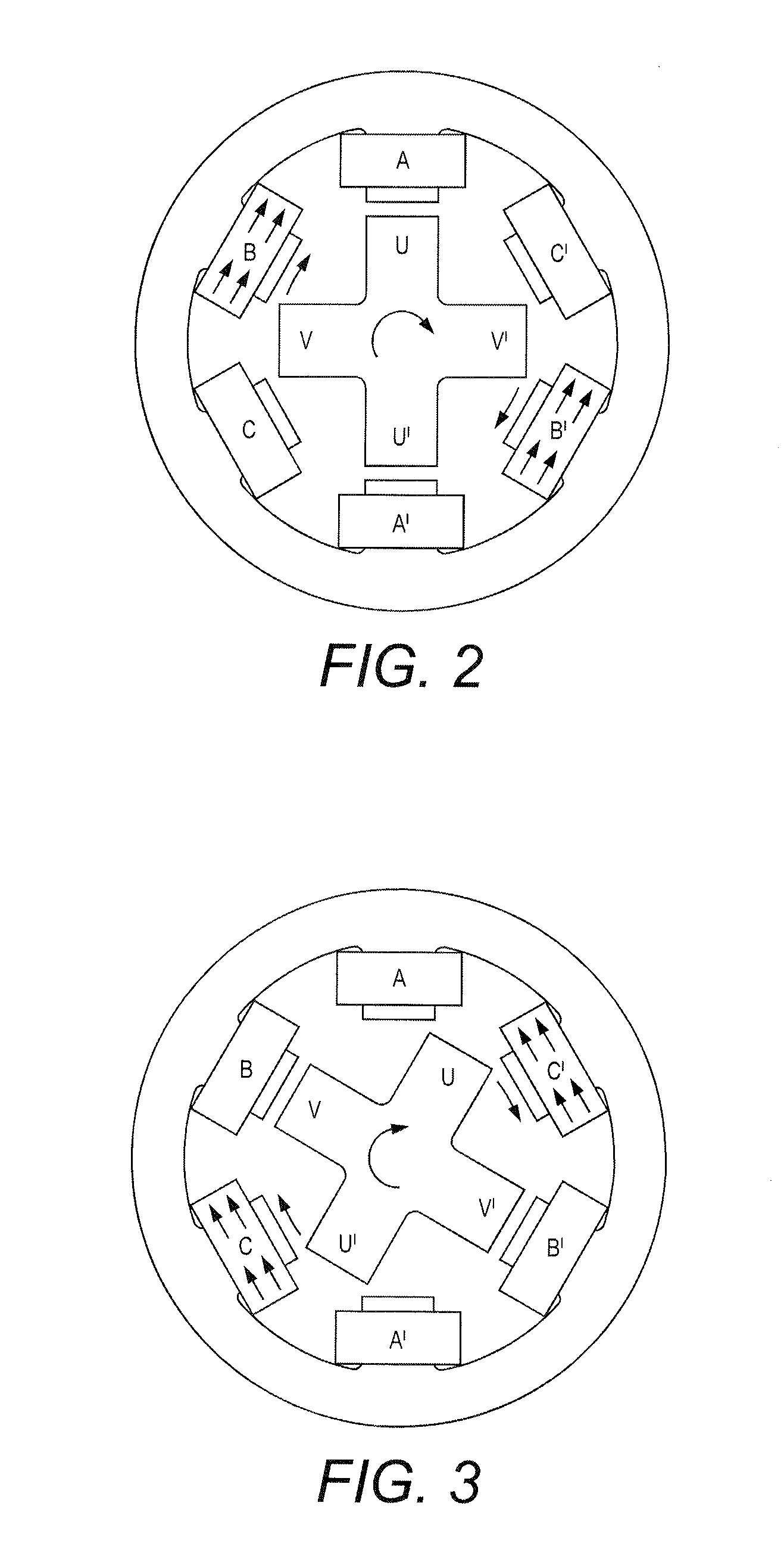
Figure 3
Abstract
Description
FIELD OF THE INVENTION
[0001] The present invention relates to switched reluctance motors and in particular to methods of starting such a motor.BACKGROUND OF THE INVENTION
[0002] A typical switched reluctance motor is shown in FIGS. 1A, 1B and 2 to 4. This example has a combination (which is frequent) of six, preferably evenly, spaced poles 2 on the stator 1 and four, preferably evenly, spaced poles 3 on the rotor 4. In this example, the poles of the stator project inwardly from a stator ring 5, the ring providing a path of low reluctance material between the stator poles.
[0003] The rotor is formed of a stack of cross-shaped laminations, also of low reluctance material. Therefore each rotor pole is connected to the diametrically opposite rotor pole by a low reluctance path, for reasons which will become apparent. So, as marked, pole U is connected by a low reluctance path to pole U′ and pole V to pole V′.
[0004] Each pole of the stator is wound with a coil 6 and the coils are arranged in p...