
Ac rotating machine control device and electric power steering device equipped with same

Active Publication Date: 2016-11-10
MITSUBISHI ELECTRIC CORP
View PDF1 Cites 19 Cited by
  • Summary
  • Abstract
  • Description
  • Claims
  • Application Information

AI Technical Summary

Benefits of technology

The present invention relates to an AC rotating machine control device and an electric power steering device including the control device. The invention provides a method for controlling the AC rotating machine in case of an abnormality in the rotational position sensor. The control device limits the drive power for the AC rotating machine until the estimated error of the rotational position falls within a predetermined range. This prevents excessive torque requirements and avoids failure of the AC rotating machine or the drive circuit due to overcurrent. The invention also restricts the drive power for the AC rotating machine until the induced voltage of the machine becomes equal to or smaller than a predetermined value. This further prevents failure of the AC rotating machine or the drive circuit. Overall, the invention provides a significant effect that could not be obtained conventionally.

Problems solved by technology

Therefore, when the rotational position sensor is abnormal, the AC rotating machine cannot be controlled, and thus it is necessary to stop an AC rotating machine.
Here, abnormalities in the rotational position sensor include abnormality of the rotational position sensor itself, and disconnection abnormality of a signal line or a feed line of the rotational position sensor.

Method used


Image

  • Ac rotating machine control device and electric power steering device equipped with same
  • Ac rotating machine control device and electric power steering device equipped with same
  • Ac rotating machine control device and electric power steering device equipped with same

Examples


embodiment 1

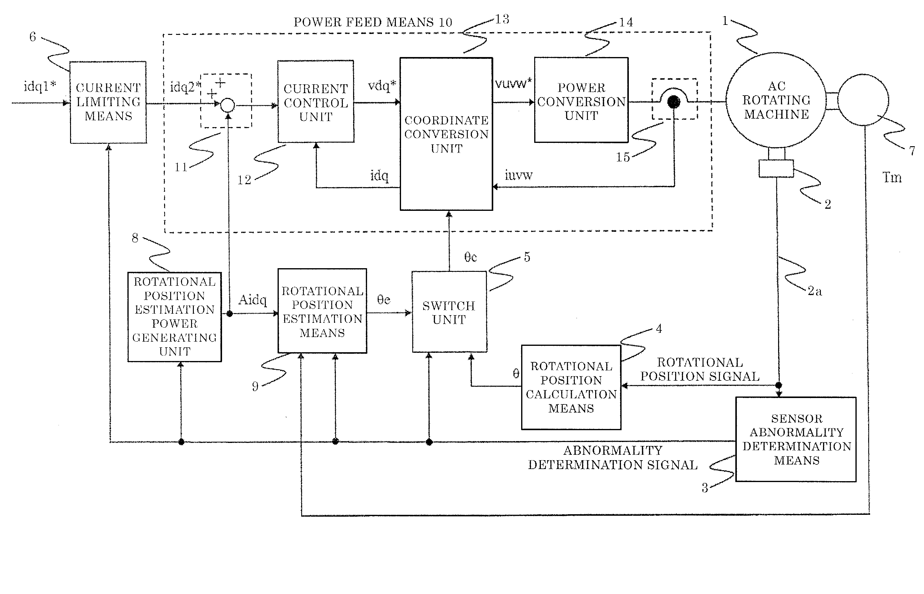
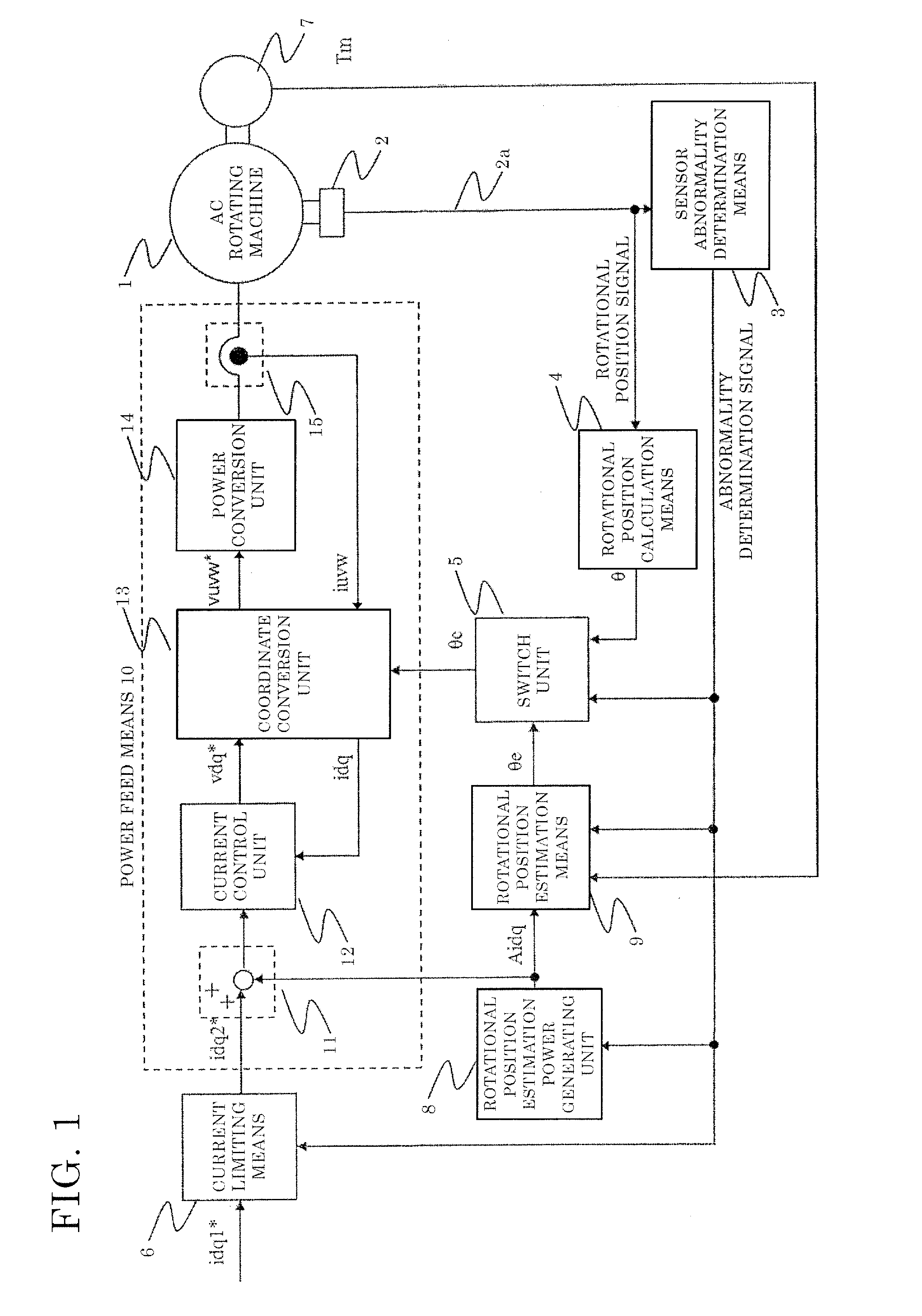
[0053]FIG. 1 is a diagram showing the entire configuration of an AC rotating machine control device in embodiment 1 of the present invention.

[0054]The first axis of the two rotational axes of an AC rotating machine 1 is set in the direction of the same phase as a rotor magnetic flux of the AC rotating machine 1, and the second axis of the two rotational axes is set in the direction orthogonal to the first axis of the two rotational axes. The first axis is referred to as d-axis and the second axis is referred to as q-axis.

[0055]In FIG. 1, the AC rotating machine 1 has three-phase windings (U phase, V phase, W phase) and is driven by AC voltage applied to the windings.

[0056]Instead of being composed of three-phase windings, the AC rotating machine 1 may be composed of a different number of windings from the three-phase windings.

[0057]A rotational position sensor 2 detects the rotational position of the AC rotating machine 1, and outputs a rotational position signal containing rotation...

embodiment 2

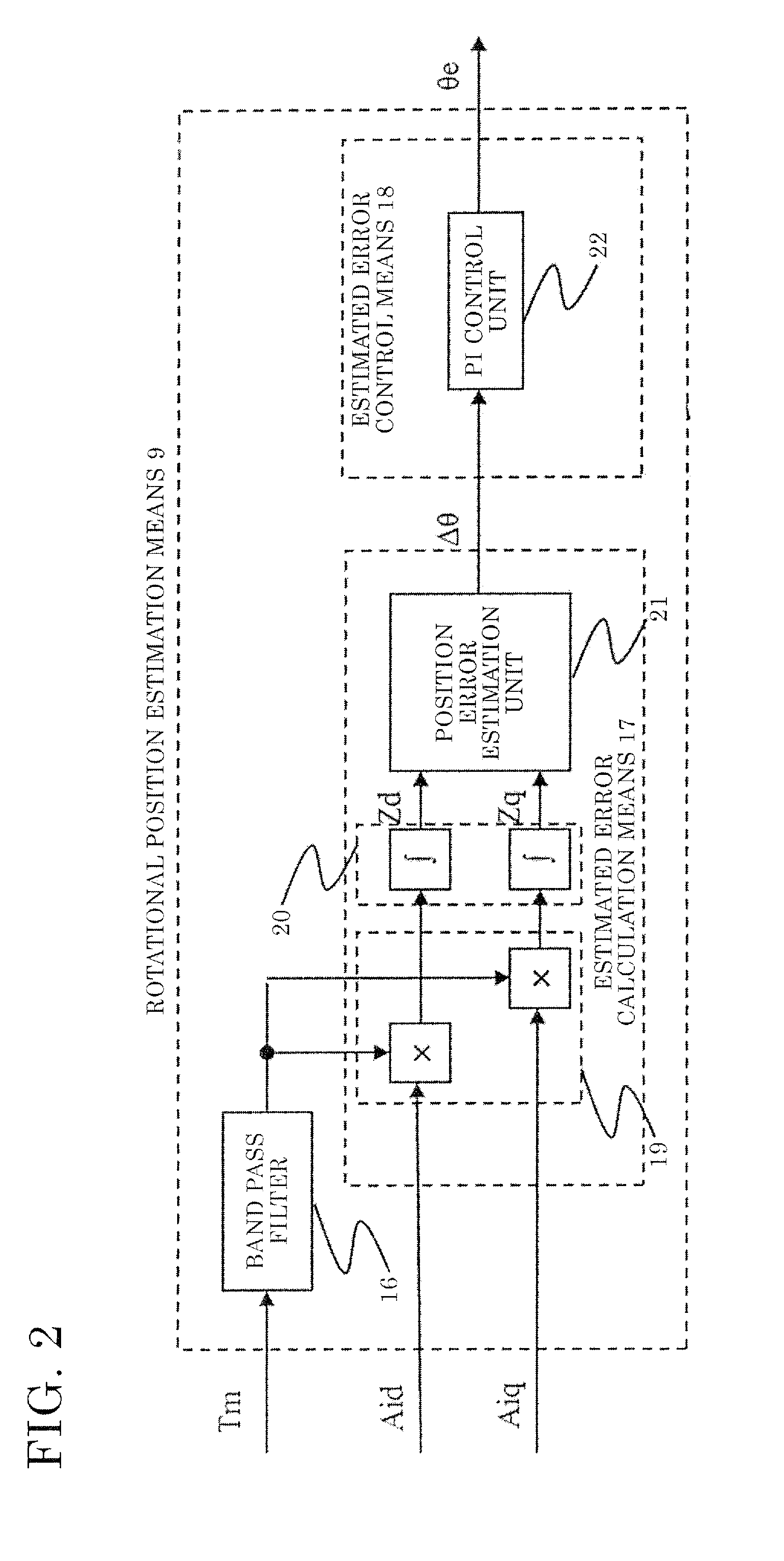
[0214]In embodiment 1, the rotational position estimation means 9 calculates the estimated rotational position θe on the basis of response in the output torque Tm when high-frequency current is supplied to the AC rotating machine 1. However, the estimated rotational position θe may be calculated by another method.

[0215]Specifically, the estimated rotational position θe may be calculated on the basis of a high-frequency component contained in detected current of the AC rotating machine when high-frequency power is supplied to the AC rotating machine.

[0216]In the present embodiment 2, in the case where high-frequency current is supplied to the AC rotating machine having saliency, in an AC rotating machine control device having known rotational position estimation means (for example, disclosed in Japanese Patent Publication No. 5069306) which is different from the rotational position estimation means 9 and which calculates the estimated rotational position θe on the basis of response i...

embodiment 3

[0249]In embodiment 1, the rotational position estimation means 9 calculates the estimated rotational position θe on the basis of response in the output torque Tm when high-frequency current is supplied to the AC rotating machine 1. However, the estimated rotational position may be calculated by another method.

[0250]Specifically, such voltage as to short-circuit windings of the AC rotating machine may be supplied, and the estimated rotational position θe may be calculated on the basis of the detected current of the AC rotating machine.

[0251]Initial estimated rotational position estimation means may be provided which calculates the initial value of the estimated rotational position θe to be calculated by the rotational position estimation means, that is, a value used immediately after switching to sensorless control, and drive power for the AC rotating machine may be limited in accordance with each rotational position estimation means, thereby eliminating reverse torque or preventing...


PUM


Abstract

This AC rotating machine control device includes: power limiting means 6 for limiting drive power supplied for driving the AC rotating machine; and power feed means 10 for, when sensor abnormality determination means 3 determines that the rotational position sensor is abnormal, on the basis of the estimated rotational position, supplying the AC rotating machine with power obtained by adding rotational position estimation power supplied for the rotational position estimation means 9 to estimate the rotational position, to the drive power limited by the power limiting means, wherein the power limiting means 6 limits drive current at least during a predetermined period since the sensor abnormality determination means 3 determines that the abnormality occurs until estimated error of the estimated rotational position falls within a predetermined range.

Description

TECHNICAL FIELD[0001]The present invention relates to an AC rotating machine control device for continuing to drive an AC rotating machine when a rotational position sensor is abnormal, and an electric power steering device including the AC rotating machine control device.BACKGROUND ART[0002]Generally, in control of an AC rotating machine, in order to supply current with an appropriate phase corresponding to the rotational position of a rotor, a rotational position sensor such as an encoder, a resolver, or a Hall element is needed.[0003]Therefore, when the rotational position sensor is abnormal, the AC rotating machine cannot be controlled, and thus it is necessary to stop an AC rotating machine.[0004]From this viewpoint, the following technology is proposed. When the rotational position sensor is abnormal, the rotational position of the rotor is estimated without using the rotational position sensor, and a rotational position signal (hereinafter, referred to as a control angle) for...

Claims


Application Information

Patent Timeline
IPC IPC(8): H02P21/18
CPCH02P21/18B62D5/046B62D5/0484B62D5/049H02P6/16H02P29/032G01R23/00H02P6/32
Inventor NAKAJIMA, SHUNSUKETSUCHIMOTO, YUYAKEZOBO, ISAOKIMPARA, YOSHIHIKO
Owner MITSUBISHI ELECTRIC CORP
Learn More