Multi-walled swing plate and swing beam

a technology of swing plate and swing beam, which is applied in the direction of building components, building types, constructions, etc., can solve the problems of difficult manufacturing, difficult scaling up, and high cost of the prior art of invention for earthquake base isolation systems, and achieves simple design, easy to understand, and increase the capacity to dissipate the kinetic energy of ground displacement.

Active Publication Date: 2016-11-17
BOWLUS LARRY +6
View PDF1 Cites 8 Cited by
  • Summary
  • Abstract
  • Description
  • Claims
  • Application Information

AI Technical Summary

Benefits of technology

[0013]The present invention advances the art of seismic wave base isolation devices for structures by its revolutionary design. It has an increased capacity to dissipate the kinetic energies of ground displacement. The present invention has a simple design and it is easy to understand also very strong and has a wider range of applications due to its increased operational parameters which goes well beyond the present prior art of base isolation systems. The preferred embodiment of this invention is the concept of the multi-walled swing plate. The present invention introduces the multi-walled swing plate element which is fundamentally a rectangular piece of rigid flat plate material with many rectangular slots cut out of the central region allowing it to straddle the many rectangular centralized walls that support this arrangement, it is what creates the self balancing form of a pendulum system that carries the load and easily absorbs and dissipates horizontal displacement earthquake energy. Another preferred embodiment of this invention will leverage the multi-walled swing plate concept to introduce the next advance that uses many swing plates placed in a row and straddling many rectangular central wall supports, thus creating the swing beam. This will be extended in the direction of its swinging movement such that the swing beam could be very long allowing it to stretch across the entire length of a foundation of a structure, if needed. Another preferred embodiment of this invention will leverage the swing beam concept to introduce the next advance that uses multiple swing beams to create a swing beam foundation column. This is a structural arrangement of swing beam layers where more than one complete swing beams is set in a layer, then another layer is placed on top of that layer rotated, usually but not limited to 60 degrees from the next layer of swing beams below it to form a foundation column. This rotating of the next layer of swing beams in the stack is what will allow the swing beam foundation column to react to horizontal ground displacement in all directions. This system can easily be scaled to accommodate the largest of structures, or with smaller dimensions used to transport sensitive cargo such as explosives or electronic equipment while riding on trucks or trains. In this configuration a cargo load can be carried by a swing beam arrangement and these arrangements need to be oriented toward the direction of travel. The present invention includes new design engineering that is very simple, yet strong and has a far wider range of applications and operational parameters with basically the same design and functional understanding. A further object of the present invention is to provide seismic protection that is inexpensive to construct the present invention uses simple construction techniques and easily obtained materials usually but not...

Problems solved by technology

A protective system for seismic base isolation and energy dissipation is well known and has many design configurations; most of the prior art of invention for earthquake base isolation systems are very expensive and of complex design.
They often require special materials also they are hard to manufacture.
Most do not scale up easily and they usually require constant maintenance.
Many are difficult to re-engineer or provide options for other applications.
Most need to be refurbished or replaced after a quake event and they have limited ground displacement range.
Many are very limited in there ability to dissipate seismic energy and most do not have energy damping options.
Many do not accommodate all three axis of movement and lastly most focuses all the quake displacement energy in to a few pivotal parts.
This system is not easy to expand, for example to get the benefit of the swing beam and carry heavier load you have to place many swing beams alongside each other and place the rows on some type of flat support such as a sheet of steel, then they are layered on top of each other three to four layers high, this is cumbersome and expensive.
This system is expensive, complex and has many unique specialized parts, also this system not easy to create and will not scale up to handle very large structures, it also will require maintenance, to continue this system is more difficult to engineer.
This system will need to be refurbished after quake events also this system cannot handle large ground displacement or dissipate very much seismic energy.
This system has no stated solution for a vertical displacement event and very limited energy damping.
This pendulum like system seems to focus all the immense energy coming from a seismic event in to a few pivotal moving parts creating huge stresses making it very difficult to have long term reliability.
This system is expensive, complex and has many unique speci...

Method used


Image

  • Multi-walled swing plate and swing beam
  • Multi-walled swing plate and swing beam
  • Multi-walled swing plate and swing beam

Examples


Embodiment Construction

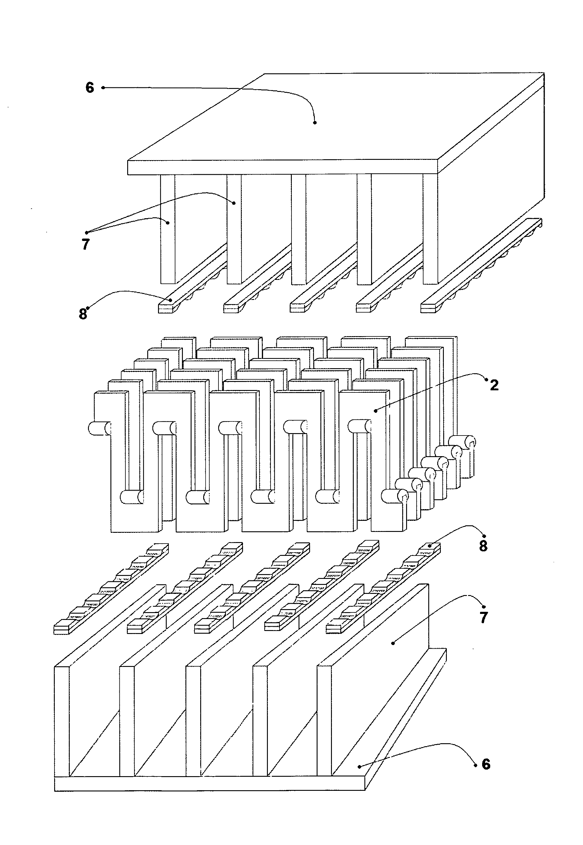
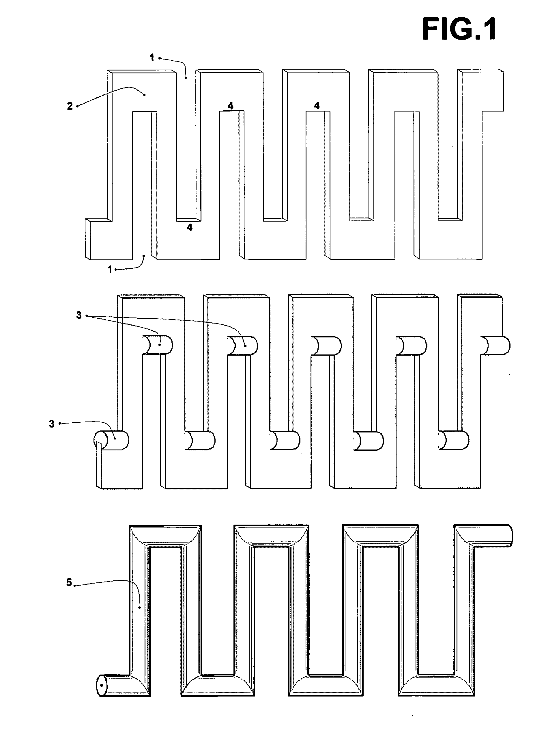
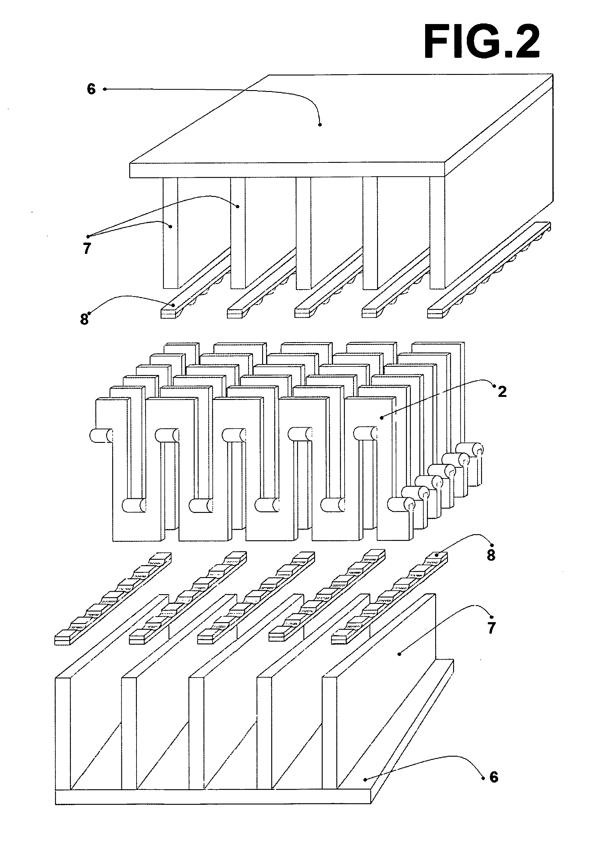
[0022]The preferred embodiment of this invention relates to a seismic wave motion isolation device for base or foundation structures and the transport of sensitive equipment. This device or apparatus will protect structures from the destructive effects of seismic wave motion in both the horizontal and vertical planes. The objects of invention are the multi-walled swing plate and the multi-walled swing beam device and a vertical unit. This seismic wave motion isolation device can be configured and built to protect the largest structures by scaling the dimensions and load capacities without altering the basic design. The dimensions are changed simply by altering length, width and height of the apparatus while the load capacities are mostly changed by increasing the size and thickness of the plate material used and the number of multi-walled swing plates used. This seismic wave motion isolation device can be configured and built to protect the most sensitive of machinery, cargo or expl...


PUM


Abstract

Seismic base isolation and energy dissipation device using a plurality of multi-walled swing plate's that are placed on many central walls that are attached to a base support structure. This arrangement creates a strong load bearing multi-walled swing beam that moves in true pendulum fashion. This system is placed between the structural load and its foundation. This seismic wave base isolation system has the purpose of absorbing seismic wave displacement energy in all directions. This unique design can scale up for very large and heavy loads or scale down to protect sensitive cargo and equipment from destructive motion. The multi-walled swing plates inside the multi-walled swing beam will provide support and absorption of motion by moving as a pendulum and therefore redirecting and dissipating seismic energy. This invention is particularly suited to reduce the initial shock of horizontal ground displacement. This system has a simple design shape and is therefore inexpensive to construct, is easy to engineer and deploy, it requires no uncommon material and requires very little maintenance or advanced electronics.

Description

CROSS-REFERENCE TO RELATED APPLICATIONS[0001]I claim the right of priority from a provisional application 61 / 998,255 June 2014 Bowlus provisionalREFERENCES CITED[0002]8,464,477 B2June 2009Bowlus et al6,725,612 B2April 2004Kim6,164,022 ADecember 2000Ishikawa et al6,966,154 B1November 2005Bierwirth7,472,518 B2January 2009Chong-Shien TsaiBACKGROUND OF THE INVENTION[0003]1. Technical Field[0004]This invention relates to Seismic base isolation and energy dissipation devices for structures. The present invention will be placed between a structural load and its foundation.[0005]2. Background Art[0006]Many devices and equipment systems exist to reduce the seismic ground motion energy that is transmitted to a structure when an earthquake event occurs. Many of these earthquake motion protective systems fall in the category of base or foundation isolation systems, as does the present invention. Some of the most complex units are those that reply on pendulum like motion where gravity supplies t...

Claims


Application Information

Patent Timeline
IPC IPC(8): E04B1/98E04H9/02
CPCE04B1/985E04H2009/026E04H9/021E04H9/0235E04H9/0215
Inventor BOWLUS, LARRYBOWLUS, RANDYBOWLUS, HEIDIBOWLUS, CONNORBOWLUS, MONIKAKAZELL, KATHERINEROMIG, AMBROSIA
Owner BOWLUS LARRY
Why Eureka
Try Eureka