Time-of-Flight Analysis of a Continuous Beam of Ions by a Detector Array

a detector array and continuous beam technology, applied in mass spectrometers, particle separator tubes, electrical equipment, etc., can solve the problems of insufficient detector capacity, inability to detect ions in time, and inability to uniformly distribute m/z values of ions

Inactive Publication Date: 2016-11-17
DH TECH DEVMENT PTE
View PDF5 Cites 6 Cited by
  • Summary
  • Abstract
  • Description
  • Claims
  • Application Information

AI Technical Summary

Benefits of technology

[0003]The primary cause of detector saturation in existing TOF MS analyzers is that ions are bunched into packets and sent in pulses toward a single detector. Ions representing a wide range of mass-to-charge (m / z) ratios spread out as they fly toward the detector—ions with smaller m / z flying faster and arriving at the detector sooner. The spreading of ions makes it easier for the detector to record arriving ions by reducing the frequency of coincident or nearly coincident arrivals.

Problems solved by technology

A key problem in current time-of-flight mass spectrometers (TOF MS) is inadequate detector capacity.
The primary cause of detector saturation in existing TOF MS analyzers is that ions are bunched into packets and sent in pulses toward a single detector.
Unfortunately, the m / z values of ions are not uniformly distributed; instead, mass spectra consist of discrete impulses.
These spikes of ions, together with intense ion sources, provide extremely challenging conditions for ion detection that current detectors cannot handle.
Although detector saturation is prevented by attenuating the beam, quantification accuracy for low-abundance species is severely compromised in MS-I analysis.

Method used


Image

  • Time-of-Flight Analysis of a Continuous Beam of Ions by a Detector Array
  • Time-of-Flight Analysis of a Continuous Beam of Ions by a Detector Array
  • Time-of-Flight Analysis of a Continuous Beam of Ions by a Detector Array

Examples


Embodiment Construction

Computer-Implemented System

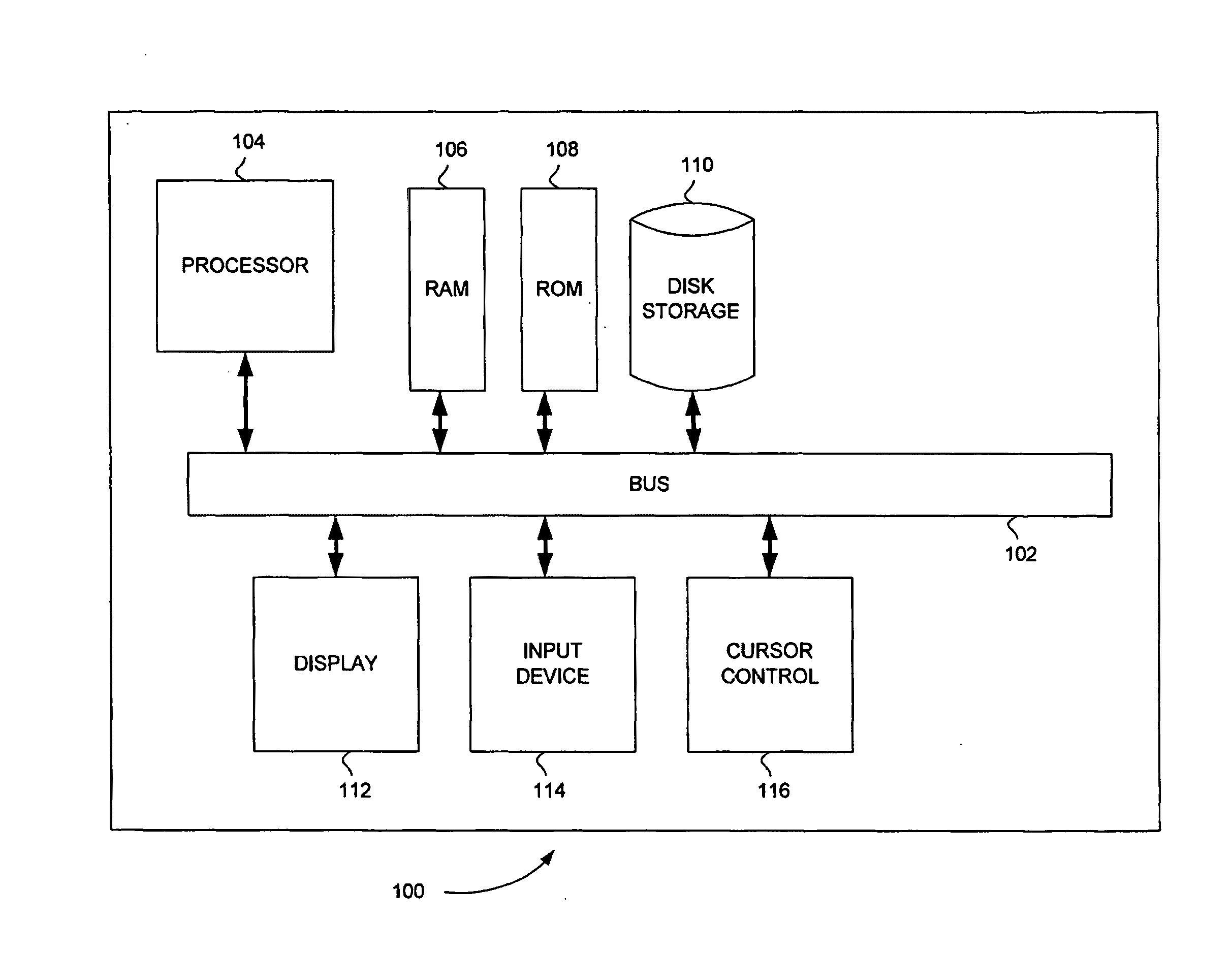
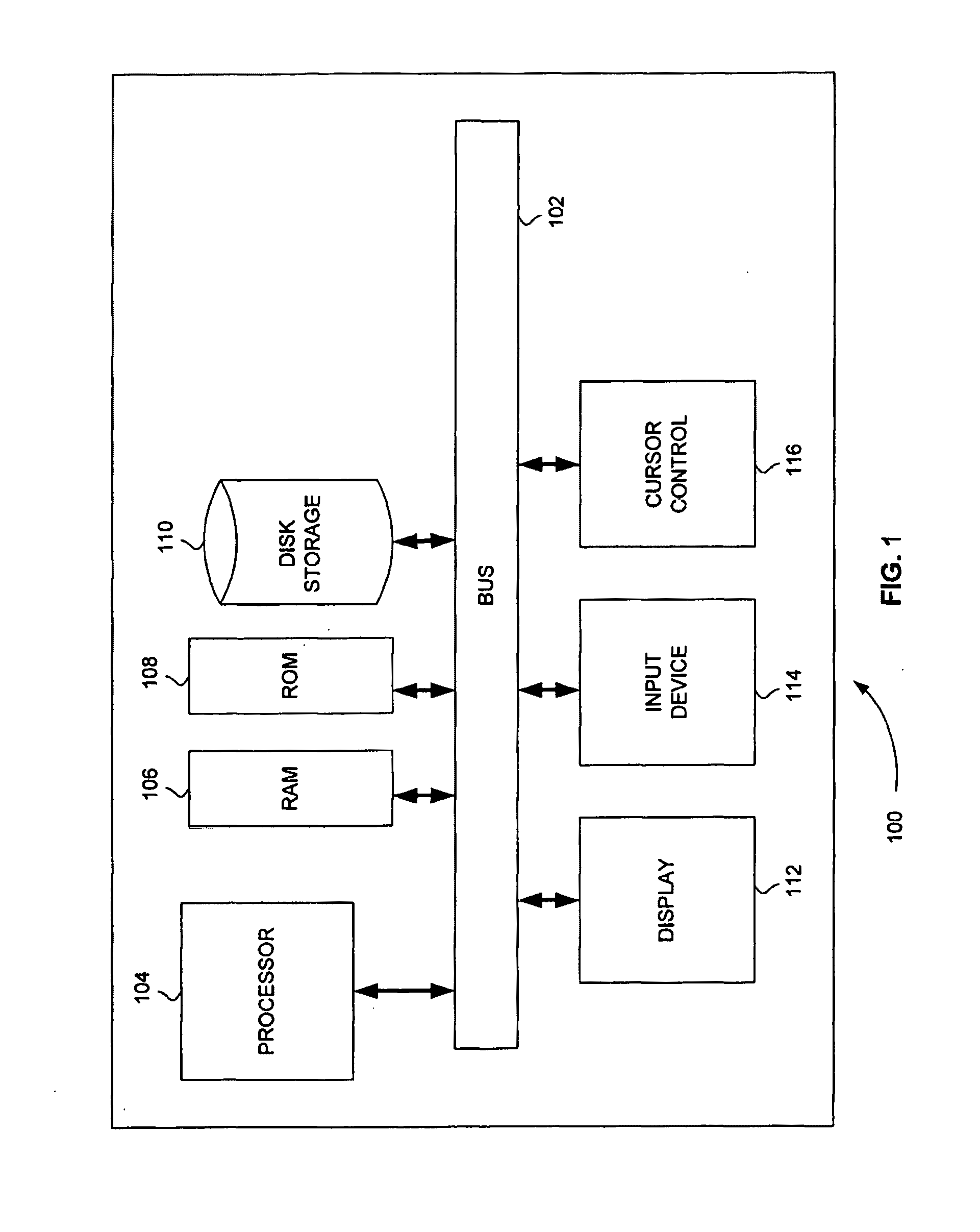
[0031]FIG. 1 is a block diagram that illustrates a computer system 100, upon which embodiments of the present teachings may be implemented. Computer system 100 includes a bus 102 or other communication mechanism for communicating information, and a processor 104 coupled with bus 102 for processing information. Computer system 100 also includes a memory 106, which can be a random access memory (RAM) or other dynamic storage device, coupled to bus 102 for storing instructions to be executed by processor 104. Memory 106 also may be used for storing temporary variables or other intermediate information during execution of instructions to be executed by processor 104. Computer system 100 further includes a read only memory (ROM) 108 or other static storage device coupled to bus 102 for storing static information and instructions for processor 104. A storage device 110, such as a magnetic disk or optical disk, is provided and coupled to bus 102 for storing infor...


PUM


Abstract

Systems and methods are provided for time-of-flight analysis of a continuous beam of ions by a detector array. A sample is ionized using an ion source to produce a continuous beam of ions. An electric field is applied to the continuous beam of ions using an accelerator to produce an accelerated beam of ions. A rotating magnetic and / or electric field is applied to the accelerated beam to separate ions with different mass-to-charge ratios over an area of a two-dimensional detector using a deflector located between the accelerator and the two-dimensional detector. An arrival time and a two-dimensional arrival position of each ion of the accelerated beam are recorded using the two-dimensional detector. Alternatively, an electric field that is periodic with time is applied in order to sweep the accelerated beam over a periodically repeating path on the two-dimensional rectangular detector.

Description

CROSS REFERENCE TO RELATED APPLICATION[0001]This application claims the benefit of U.S. Provisional Patent Application Ser. No. 61 / 922,696, filed Dec. 31, 2013, the content of which is incorporated by reference herein in its entirety.INTRODUCTION[0002]A key problem in current time-of-flight mass spectrometers (TOF MS) is inadequate detector capacity. Inadequate detector capacity manifests itself in two ways: 1) detector saturation by individual ion species; 2) artifacts in the mass spectrum caused by two or more ion species with very small differences in their mass-to-charge ratios, including distortions in the observed intensities or m / z values, spurious merging of distinct m / z values, or complete loss of some ion species that arrive at the detector at nearly the same time because of their small differences in mass-to-charge ratio.[0003]The primary cause of detector saturation in existing TOF MS analyzers is that ions are bunched into packets and sent in pulses toward a single dete...

Claims


Application Information

Patent Timeline
Patent Type & Authority Applications(United States)
IPC IPC(8): H01J49/40H01J49/22H01J49/00H01J49/20
CPCH01J49/40H01J49/0031H01J49/22H01J49/20H01J49/025
Inventor GROTHE, JR., ROBERT ALOIS
Owner DH TECH DEVMENT PTE
Why Eureka
Try Eureka