

Coordinated Beamforming Method and Apparatus Based on Partial Interference Alignment
a beamforming method and partial interference technology, applied in the field of coordinated multiple point transmission in wireless communication, can solve the problems of system inevitably having a remarkable performance loss, difficulty in implementing alignment, and high implementation complexity, and achieve the effect of effectively improving the system sum rate and minimizing the performance loss caused by quantization
- Summary
- Abstract
- Description
- Claims
- Application Information
AI Technical Summary
Benefits of technology
Problems solved by technology
Method used
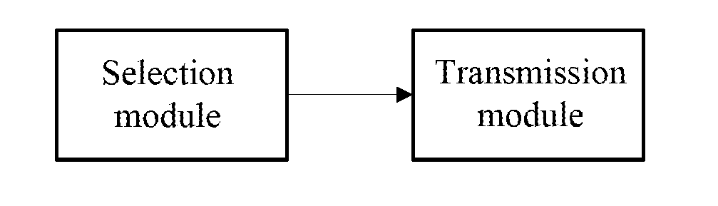
Image

Examples
embodiments
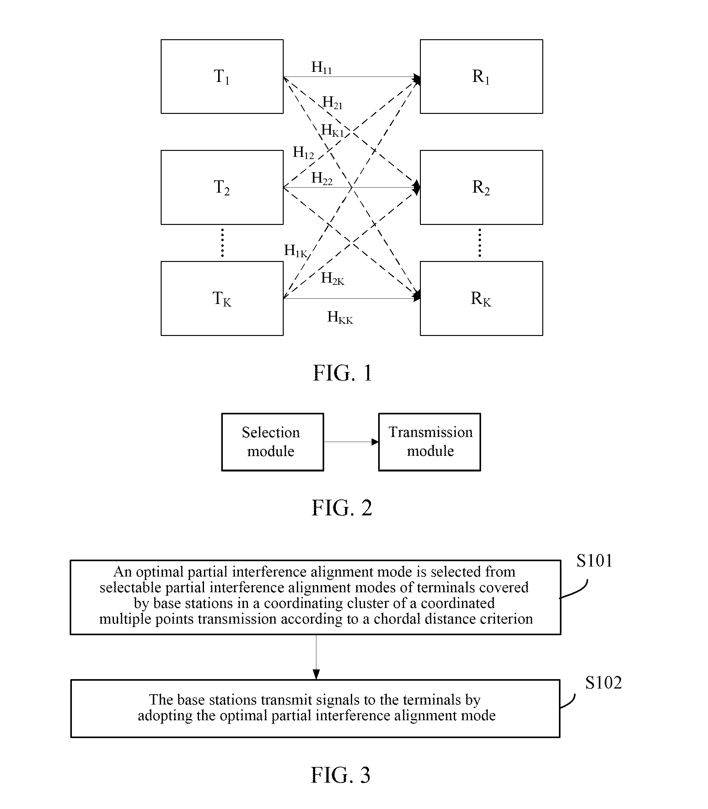
[0069]This embodiment mainly aims at beamforming of cell edge users (terminals), and considering one interference channel system, as shown in FIG. 1, a Multiple-Input Multiple-Output (MIMO) interference channel model is provided. In the FIG. 1, full lines denote useful channels; dashed lines denote interference channels; T denotes a transmitting end (base station); R denotes a receiving end (terminal); there are K base stations Tk and K terminals Rk in a coordinating cluster of a Coordinated Multiple Points (CoMP), K is an integer greater than 3, each base station serves one terminal, the base stations respectively and independently transmit dk=d (k=1, 2, . . . , K) data streams to corresponding target terminals, and dk is an integer greater than or equal to 1 and less than or equal to M / (K-1), and “ / ” denotes division operation. Each base station and each terminal in cells are respectively provided with M antennas. Inter-user interferences are not considered, only inter-cell interf...
application example 1
[0117]A 4-cell 4-terminal scenario as shown in FIG. 6 is adopted. It is supposed that the numbers of antennas configured at each base station and at each terminal are the same, and each base station transmits d data streams to the corresponding terminal. If the alignment modes of the four terminals are not fixed, totally there are 69 valid alignment modes, herein FIG. 6(a) illustrates all alignment modes after fixing interference alignment modes of . Since alignment modes of R2 and R3 are not fixed, R2 includes three alignment modes in which T1T3, T1T4 and T3T4 are respectively aligned to one space. Similarly, R3 has three alignment modes. Through combination, the two terminals totally have nine alignment modes. As shown in FIG. 7, seven alignment modes thereof are valid. FIG. 6(b) is a situation that alignment modes of 4 terminals are fixed and illustrates one of seven valid alignment modes.
[0118]An interference channel system as shown in FIG. 1 is considered, herein K=4, and in th...
application example 2
[0154]In another application example, by adopting the same scenario and the same steps of solving the optimal partial interference alignment mode, after four base stations transmit signals to four terminals by adopting a precoding matrix group V1, V2, V3, V4opt corresponding to the optimal alignment mode, the receiving ends (terminals) may perform system sum rate performance comparison by adopting receiving algorithms which are respectively a zero forcing algorithm and an MMSE algorithm.
[0155]After step S406, the method further includes steps for calculating the system sum rate under an ideal CSI condition, including:
[0156]In S407b, a receiving matrix Uk is solved at the receiving end;
[0157](a) ZF receiving algorithm
[0158]firstly let
H1=[H12V2, H13V3, H14V4]
H2=[H21V1, H23V3, H24V4]
H3=[H31V1, H32V2, H34V4]
H4=[H41V1, H42V2, H43V3] (20)
[0159]then SVD (Singular Value Decomposition) is performed on a matrix Hk to obtain
Hk=[U_kU~k][Σk0][V_kHV~kH]
[0160]and a zero-forcing receiving matrix i...
PUM
 Abstract
Description
Claims
Application Information