

Coating Soluble Tooling Inserts
a tooling insert and coating technology, applied in the direction of coatings, liquid surface applicators, other domestic articles, etc., can solve the problems of undesired “marking” on the formed part, the tooling insert may not be easily withdrawn from the part, and the tooling insert cannot be easily withdrawn. the effect of surface tension
- Summary
- Abstract
- Description
- Claims
- Application Information
AI Technical Summary
Benefits of technology
Problems solved by technology
Method used
Image

Examples
Embodiment Construction
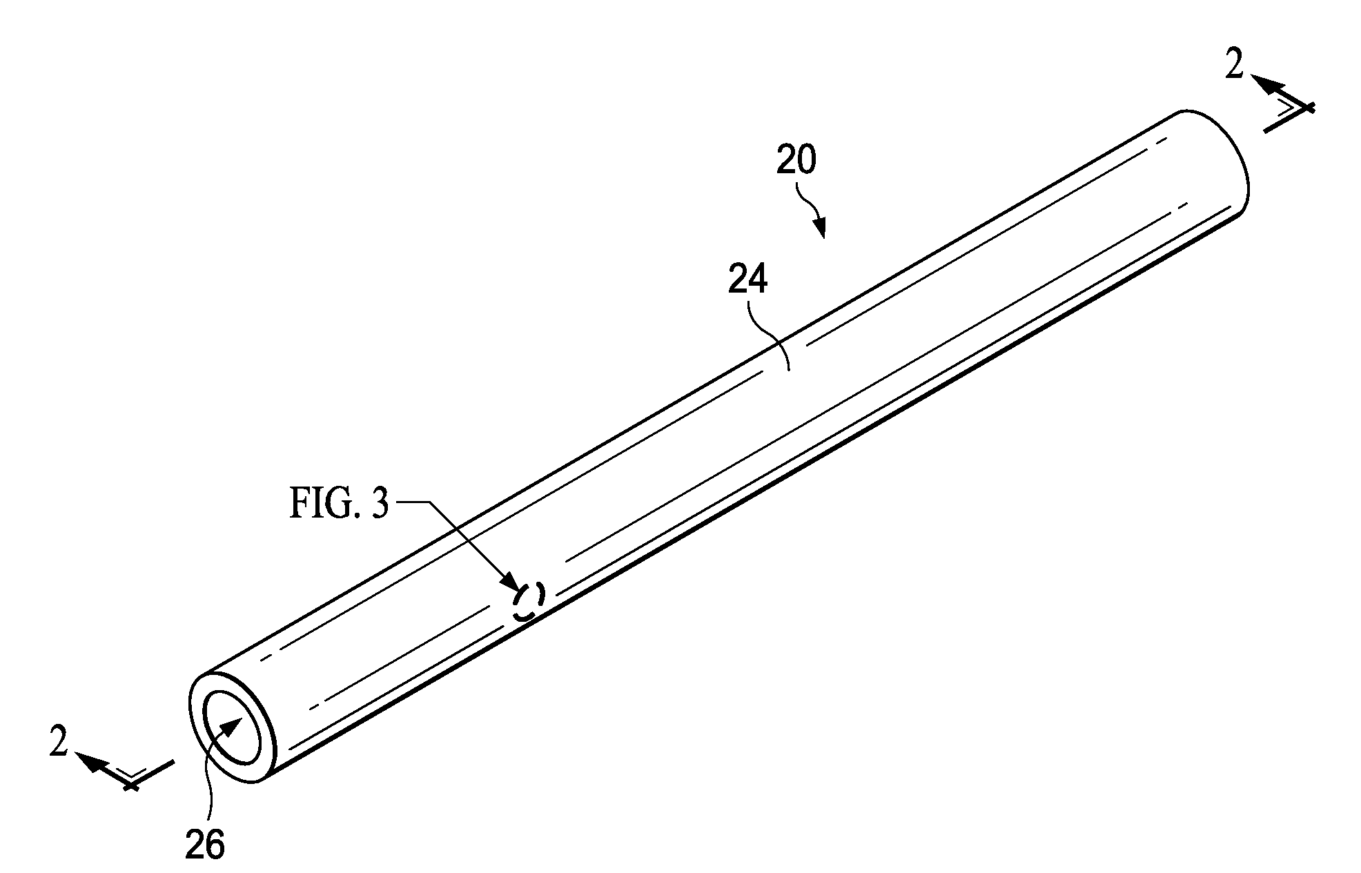
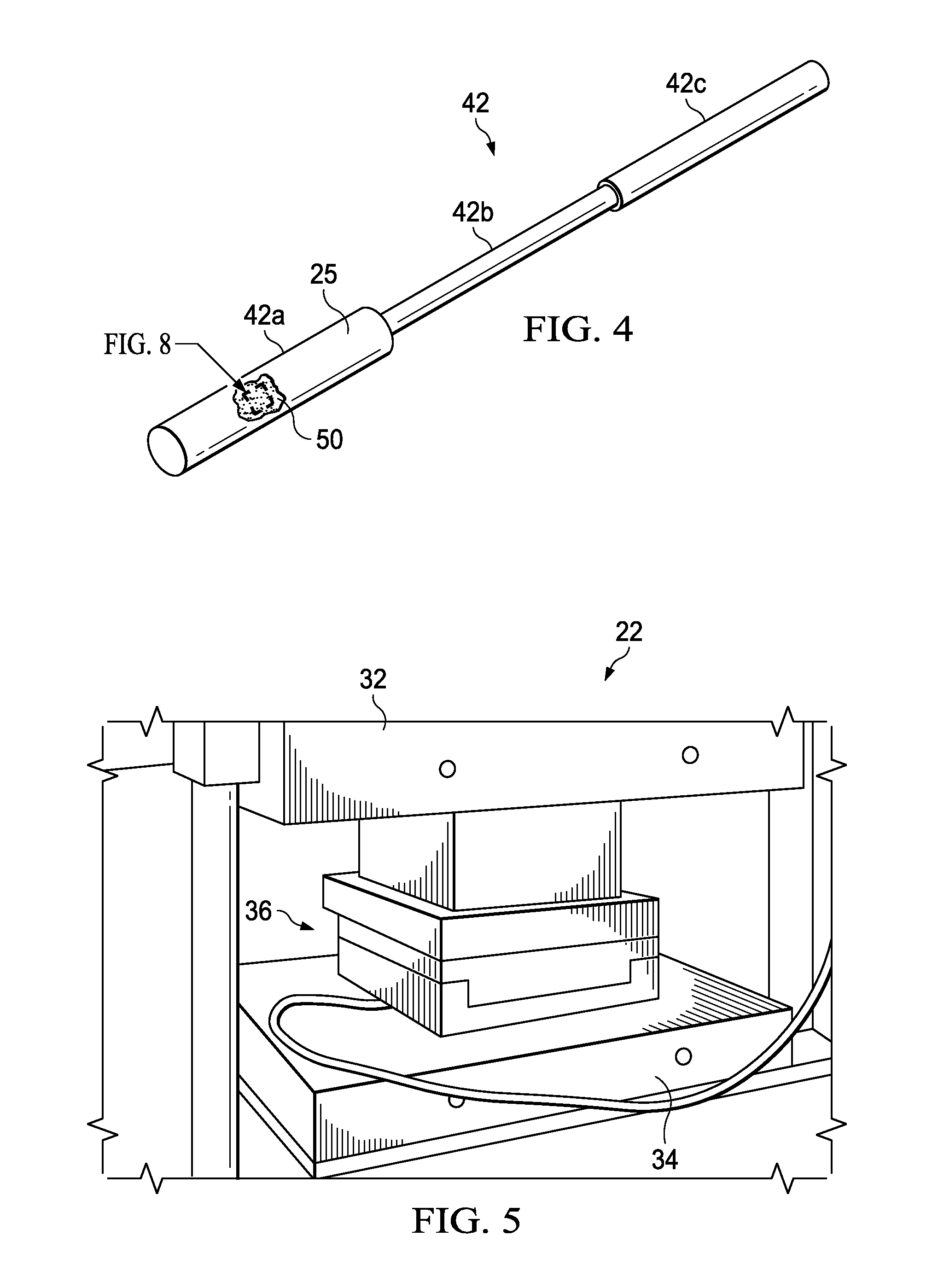
[0031]Referring first to FIGS. 1-6, a composite plastic part 20, such as a tube 20 (FIG. 1), may be molded in a heated mold tool 36 (FIG. 5) using a compression molding press 22. The mold tool 36 is compressed between upper and lower heated platens 32, 34 of the compression molding press 22. Although a simple compression molding press 22 is illustrated, the disclosed embodiments may be employed in connection with other types of molding processes, including but not limited to continuous compression molding or extrusion. Moreover, the disclosed embodiments may be employed to produce composite plastic parts, including fiber reinforced laminate parts, using any of a variety of other manufacturing processes, including but not limited to, injection molding.
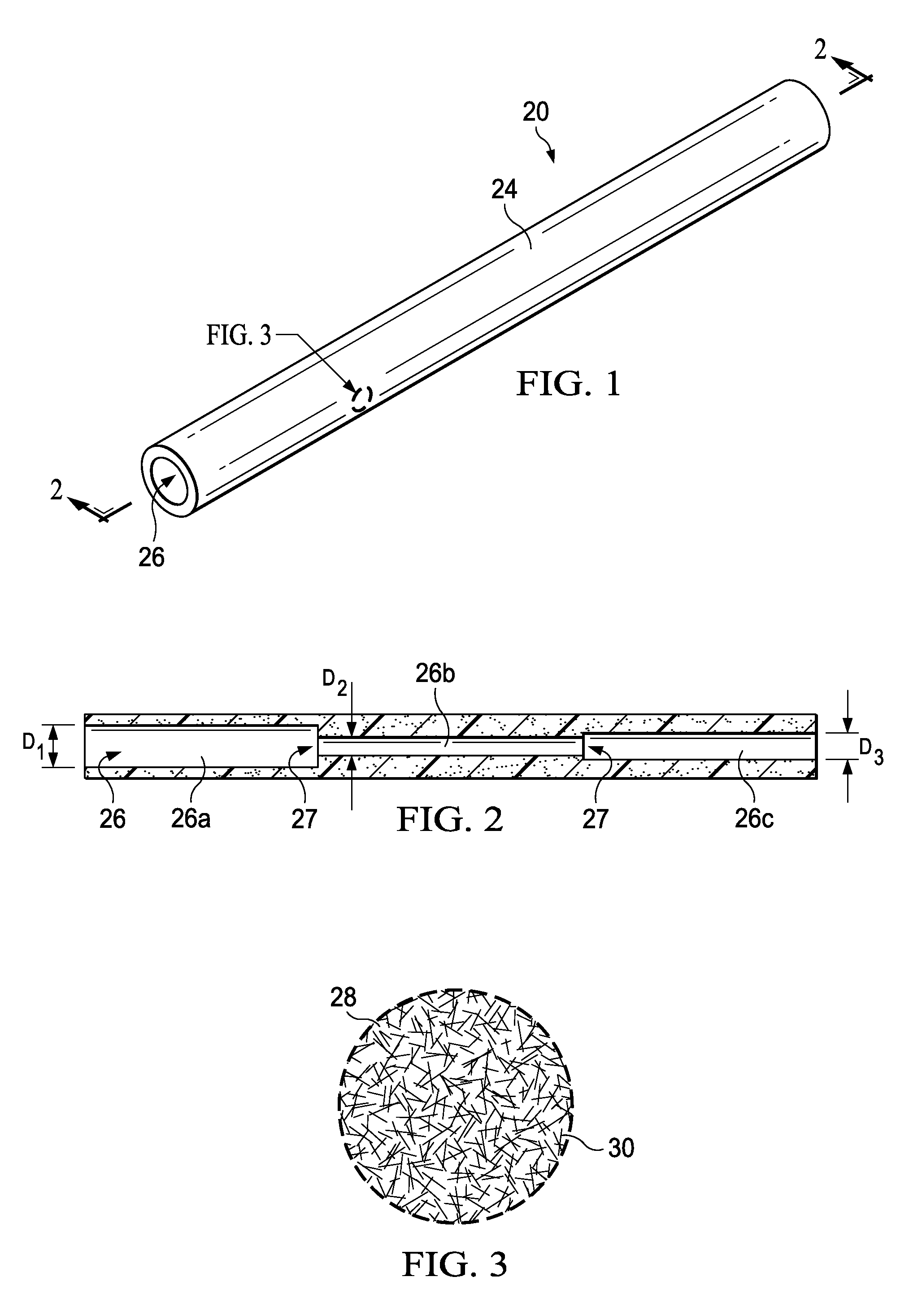
[0032]The illustrated tube 20 is of a unitary, molded construction, comprising a cylindrical body 24 having an axial bore 26. The axial bore 26 may include sections 26a, 26b, 26c, respectively having different diameters D1, D2, D3 that ...
PUM
| Property | Measurement | Unit |
|---|---|---|
| temperature | aaaaa | aaaaa |
| temperatures | aaaaa | aaaaa |
| surface irregularities | aaaaa | aaaaa |
Abstract
Description
Claims
Application Information