Magnetic transmission apparatus

a transmission apparatus and magnetic field technology, applied in the direction of permanent magnet clutches/brakes, electrical apparatus, dynamo-electric machines, etc., can solve the problems of friction loss, severe limitation of mechanical gears, and contact between moving elements of mechanical gears that will definitely bring a plurality of troubles, so as to improve the degree of magnetic field coupling and the torque density of the magnetic transmission apparatus.

Active Publication Date: 2016-11-24
SOUTH UNIVERSITY OF SCIENCE AND TECHNOLOGY OF CHINA
View PDF2 Cites 6 Cited by
  • Summary
  • Abstract
  • Description
  • Claims
  • Application Information

AI Technical Summary

Benefits of technology

[0006]The invention is intended to provide a magnetic transmission apparatus which possesses an axially and radially mixed magnetic circuit, and is capable of taking full advantage of the magnetic modulation space and improving the torque density.
[0024]The magnetic transmission apparatus of the present application possesses a axially and radially mixed magnetic circuit because the first permanent magnet and the third permanent magnet are magnetized axially and the second permanent magnet is magnetized radially; the magnetic field produced by the first permanent magnet, the second permanent magnet and the third permanent magnet is modulated by the magnetic regulation ring; more magnetic field harmonic in the axial air gap and radial air gap will contribute to the transmission of the torque, thereby taking full advantage of the finite geometric space; the orthogonality and the specific position relation between the second permanent magnet and the third permanent magnet force the magnetic field lines produced by the second permanent magnet and the third permanent magnet to one side of the first rotating part, thereby improving the degree of coupling of the magnetic field, and the torque density of the magnetic transmission apparatus.

Problems solved by technology

Therefore, the contact between the moving elements of the mechanical gears will definitely bring a plurality of troubles such as friction loss, vibration, noise, lubrication requirement and periodical maintenance requirement.
Mechanical gears are severely limited in circumstances concerning fluid-flow control, such as in an artificial blood pump or a poison gas pipe pump, because the mechanical gears cannot realize complete isolation between the output end and the input end.
Thus, there may often be the hidden danger of fluid leakage, and the failure of sealing measure will bring severe result.
A giant gear box will unavoidably increase the volume and weight of a system, and improve the complexity of the system.
Furthermore, the mechanical gears are engaged with each other rigidly with teeth, once the torque is beyond the affordability force, security accidents are likely to happen.
The magnetic regulation ring located between the inner rotor and the outer rotor brings great trouble for designing, manufacturing, fixing and supporting the structure of the magnetic regulation ring, since each of the magnetic regulation iron cores of the magnetic regulation ring of the magnetic gear cannot be short-connected together in order to improve the performance of the magnetic regulation performance of the iron core.
Technical solutions of the prior art remedy the above mentioned issues, however, the technical solutions improve the complexity of the structure, some of them even sacrifice the performance of the magnetic gear.
However, the above-mentioned radial magnetic gear and axial magnetic gear possess a sole magnetic circuit, which is either radial or axial, and the design and the manufacturing of the magnetic regulation mechanism of the radial magnetic gear are very troublesome.

Method used


Image

  • Magnetic transmission apparatus
  • Magnetic transmission apparatus
  • Magnetic transmission apparatus

Examples


Embodiment Construction

[0036]The technical solutions of the embodiments in the invention will be described clearly and completely in combination of the figures of the embodiments in the invention.

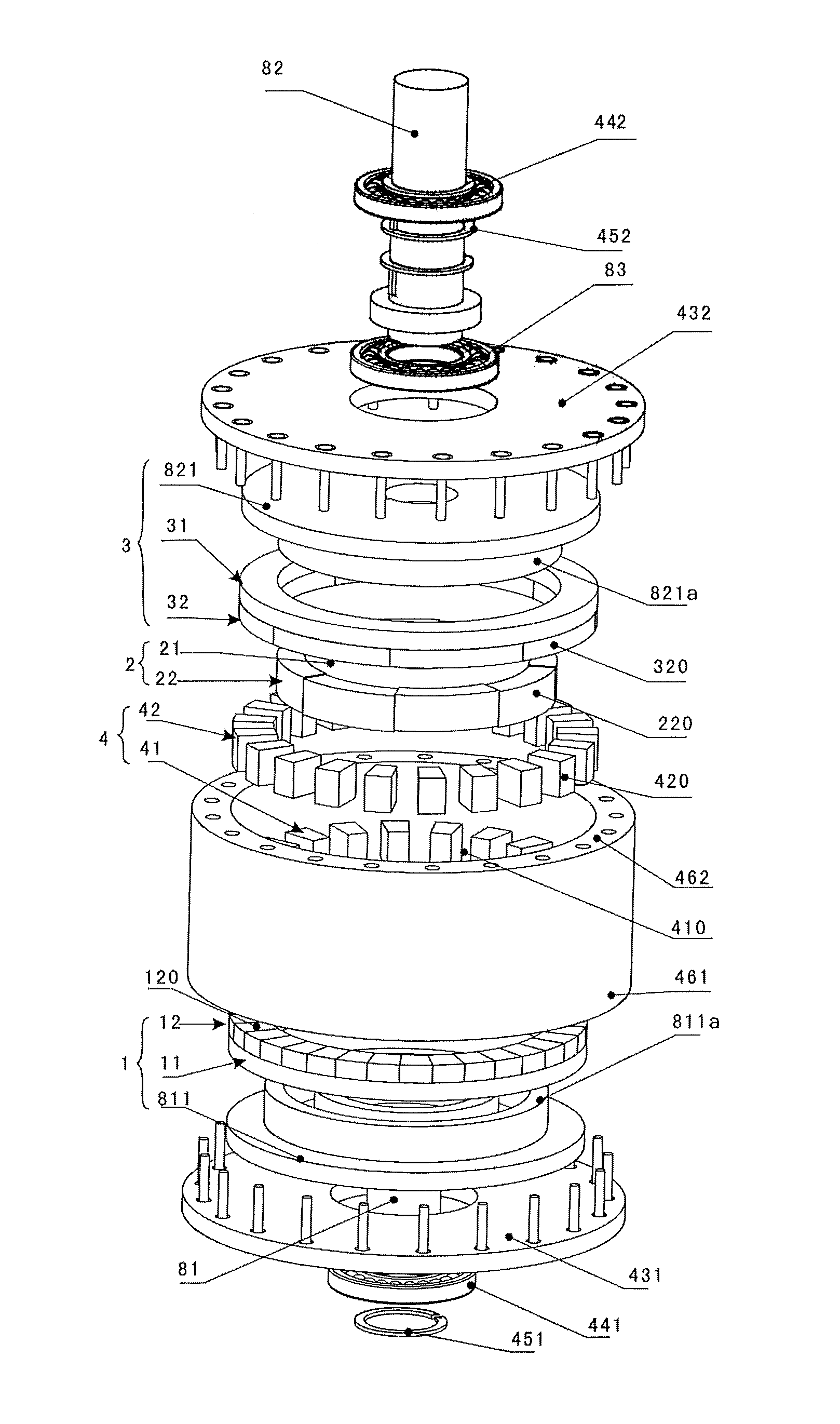
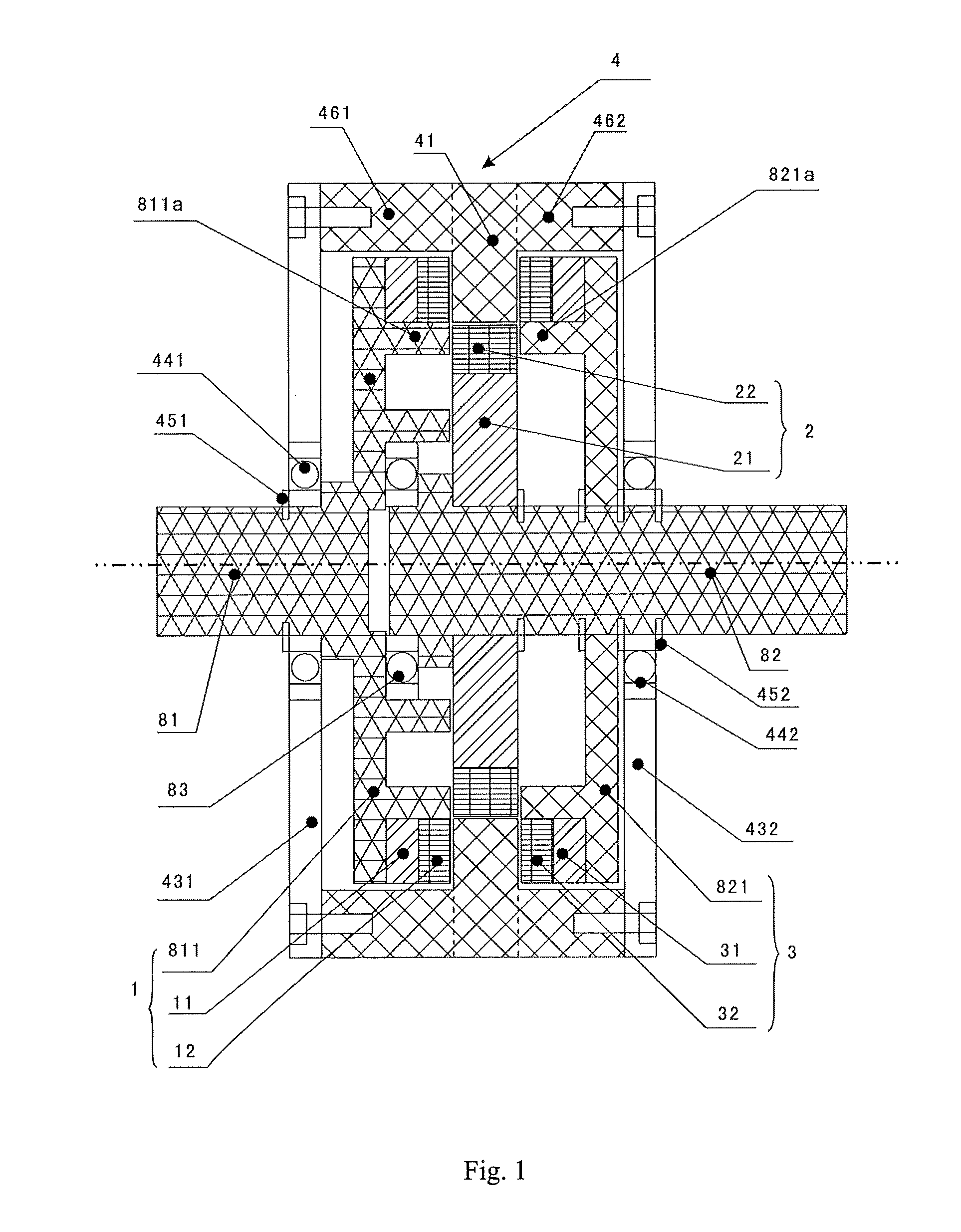
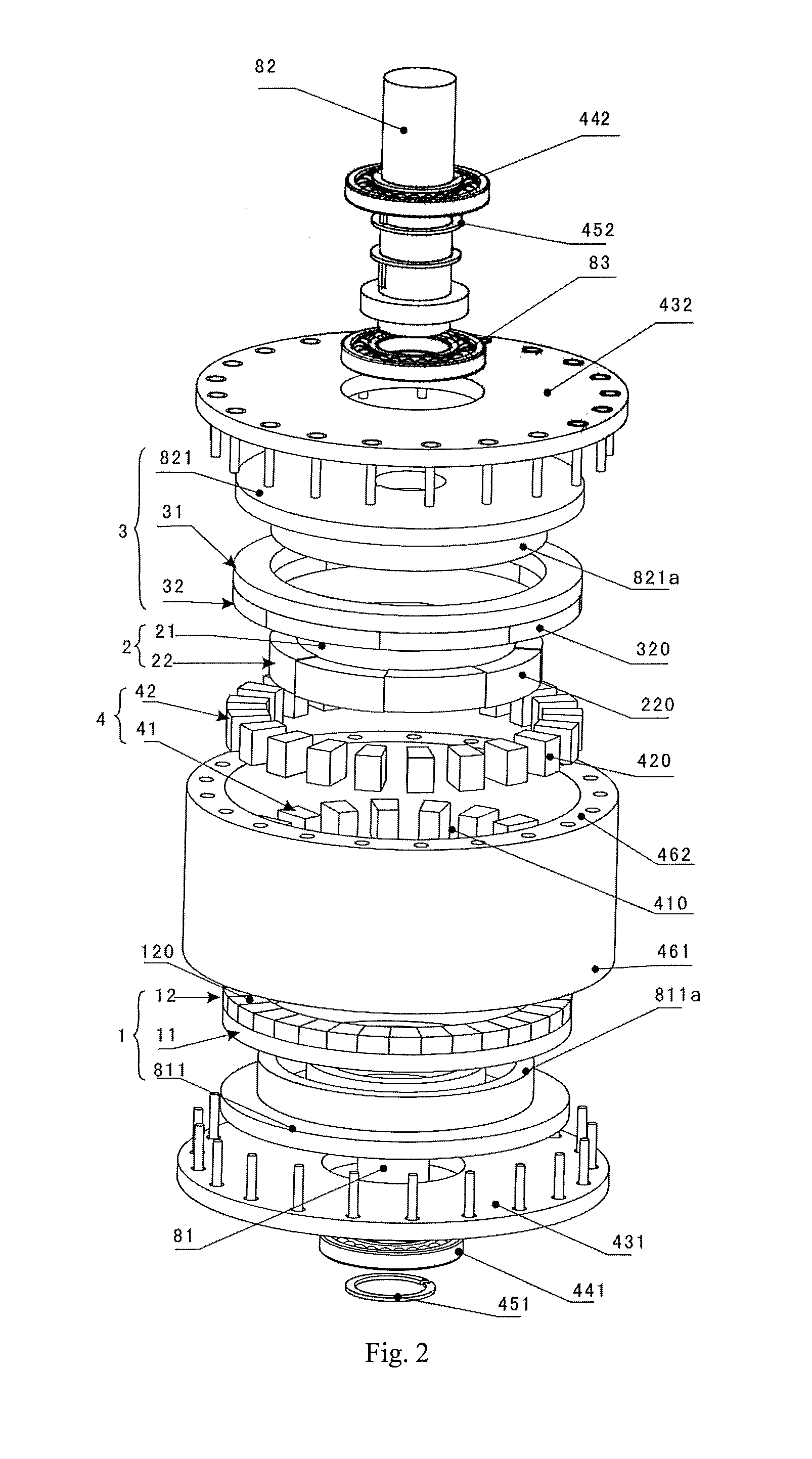
[0037]Please refer to FIGS. 1-6, one embodiment of the invention provides a magnetic transmission apparatus which includes a first rotating shaft 81, a second rotating shaft 82, a first rotating part 1, a second rotating part 2, a third rotating part 3 and a still part 4. The first rotating shaft 81, the second rotating shaft 82, the first rotating part 1, the second rotating part 2, and the third rotating part 3 are all rotatably arranged relative to the still part 4. The first rotating shaft 81 and the second rotating shaft 82 are arranged coaxially, and both distributed along an axial direction. It should be understood that in the embodiment, the terms “axial”, “radial” and “circumferential” are all relative to the central axes of the first rotating shaft 81 and the second rotating shaft 82.

[0038]The first rot...


PUM


Abstract

A magnetic transmission apparatus is disclosed, wherein the magnetic transmission apparatus includes a still part (4), a first rotating shaft (81), a second rotating shaft (82), a first rotating part (1), a second rotating part (2), and a third rotating part (3); the first rotating part (1) is rigidly connected with the first rotating shaft (81); the second rotating part (2), the third rotating part (3) are fixed on the second rotating shaft (82); the first rotating part (1), the second rotating part (2), and the third rotating part (3) are successively distributed along an axial direction; the still part (4) includes a magnetic regulation seat (41) and a magnetic regulation ring (42); the second rotating part (2) is located inside the magnetic regulation ring (42); the first rotating part (1) includes a first iron core (11), a first permanent magnet (12), and a first support part (811); the second rotating part (2) includes a second iron core (21), and a second permanent magnet (22); the third rotating part (3) includes a third iron core (31), a third permanent magnet (32), and a second support part (821); the first iron core (11), the first permanent magnet (12), the magnetic regulation ring (42), the third permanent magnet (32) and the third iron core (31) are successively distributed along the axial direction. The first permanent magnet (12) and the third permanent magnet (32) are magnetized alternately and axially; the second permanent magnet (22) is magnetized alternately radially. The magnetic transmission apparatus has an axially and radially mixed magnetic circuit and can take full advantage of the magnetic modulation space and improve the torque density.

Description

FIELD OF THE INVENTION[0001]The present application relates to the field of magnetism-energy transformation technology and power transmission apparatus manufacturing technology, especially to a magnetic transmission apparatus.BACKGROUND OF THE INVENTION[0002]As known to all, mechanical gear apparatuses have been applied widely in the industry field. It's not hard to find out that mechanical gears are composed of a plurality of individual moving elements, and the power transmission between the a plurality of moving elements is achieved by the engagement of teeth arranged on peripheries of the moving elements. Therefore, the contact between the moving elements of the mechanical gears will definitely bring a plurality of troubles such as friction loss, vibration, noise, lubrication requirement and periodical maintenance requirement. Mechanical gears are severely limited in circumstances concerning fluid-flow control, such as in an artificial blood pump or a poison gas pipe pump, becaus...

Claims


Application Information

Patent Timeline
Patent Type & Authority Applications(United States)
IPC IPC(8): H02K49/10
CPCH02K49/102H02K49/10
Inventor JIAN, LINNISHI, YUJUNWEI, JIN
Owner SOUTH UNIVERSITY OF SCIENCE AND TECHNOLOGY OF CHINA
Why Eureka
Try Eureka