Optical network controller and optical network control method

Active Publication Date: 2016-12-01
NEC CORP
View PDF6 Cites 16 Cited by
  • Summary
  • Abstract
  • Description
  • Claims
  • Application Information

AI Technical Summary

Benefits of technology

The present invention improves the use of different wavelengths in an optical network, while keeping it stable. This results in better overall performance of the network.

Problems solved by technology

A new problem, however, has been caused with respect to wavelength band allocation.
That is to say, although there are a sufficient number of empty slots in total, consecutive empty slots cannot be ensured because each empty slot is composed of short segments.
As a result, it is impossible to allocate to the optical path a wide wavelength band which allows high-capacity or long-haul communication.

Method used


Image

  • Optical network controller and optical network control method
  • Optical network controller and optical network control method
  • Optical network controller and optical network control method

Examples


first exemplary embodiment

A First Exemplary Embodiment

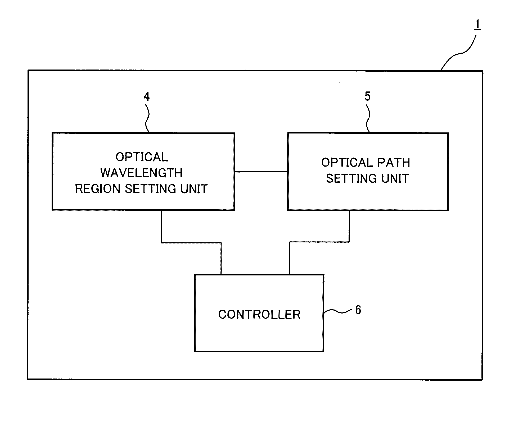
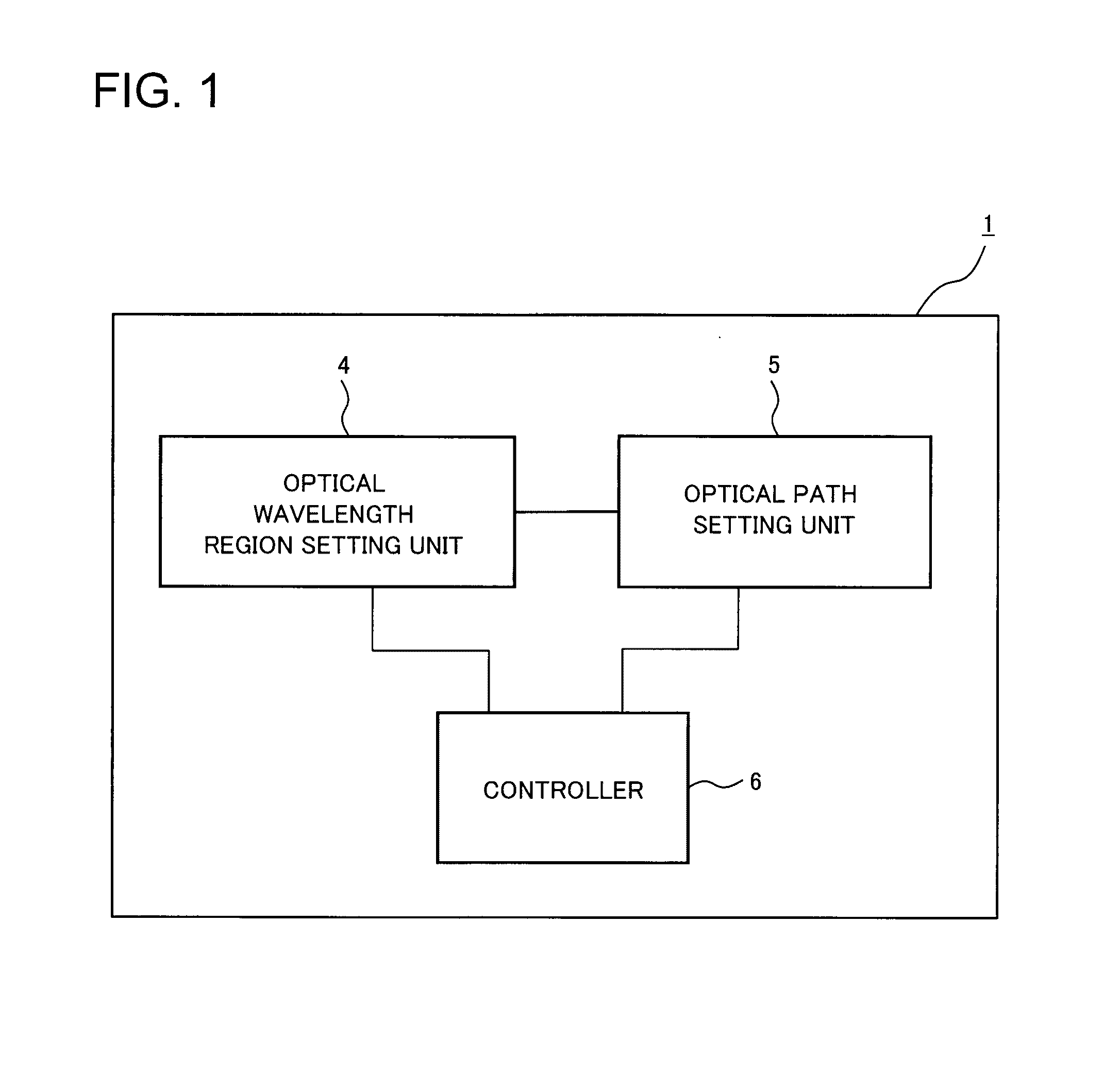
[0031]A first exemplary embodiment of the present invention will be described in detail with reference to the drawings. FIG. 1 is a block diagram illustrating a configuration of an optical network controller in accordance with the first exemplary embodiment of the present invention. The configuration of the optical network controller in accordance with the first exemplary embodiment of the present invention will be described with reference to FIG. 1.

[0032]An optical network controller 1 in accordance with the present invention controls the wavelengths in optical transmission lines between a plurality of optical nodes composing an optical network using wavelength division multiplexing system and includes an optical wavelength region setting unit 4, an optical path setting unit 5, and a controller 6.

[0033]The optical wavelength region setting unit 4 sets a wavelength region in an optical transmission line between a plurality of optical nodes composing an op...

second exemplary embodiment

A Second Exemplary Embodiment

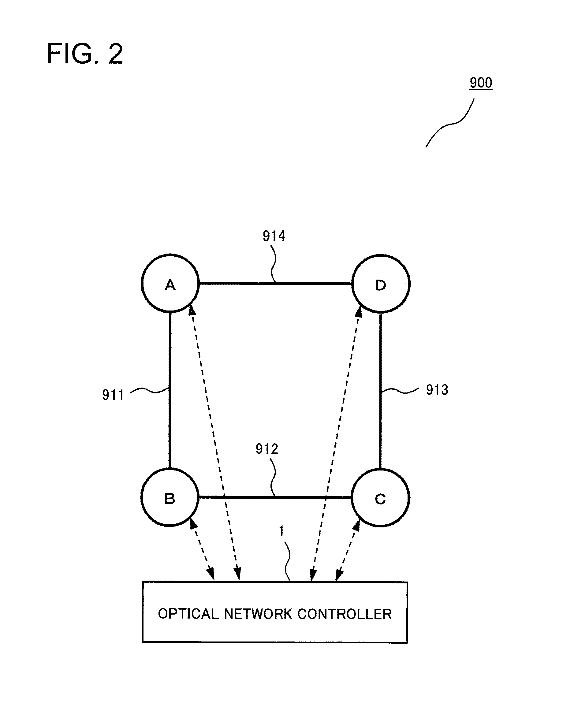
[0055]Next, a second exemplary embodiment of the present invention will be described in detail. An optical network controller in the second exemplary embodiment has the same configuration as that in the first exemplary embodiment and has a different processing operation of the wavelength defragmentation for a selected wavelength region. FIG. 7 is a conceptual diagram for explaining setting status of processing operations of the optical network controller according to the second exemplary embodiment of the present invention, and FIG. 8 is a conceptual diagram for explaining the processing operations over time of the optical network controller according to the second exemplary embodiment of the present invention. As is the case with the first exemplary embodiment, the optical network controller and the optical node are assumed to be configured as illustrated in FIG. 2 and FIG. 3. With reference to FIGS. 2, 3, 7, and 8, the processing operation of the optic...

third exemplary embodiment

A Third Exemplary Embodiment

[0080]Next, a third exemplary embodiment of the present invention will be described in detail. An optical network controller in the third exemplary embodiment has the same configuration as that in the first exemplary embodiment and has a different processing operation for allocating wavelength slots. That is to say, the third exemplary embodiment has a different processing operation for allocating wavelength slots for a new optical path.

[0081]FIG. 10 is a conceptual diagram illustrating an optical network in accordance with the third exemplary embodiment of the present invention, and illustrates a setting of first and second standby system optical paths for an active system optical path in an optical network in which ten nodes of optical nodes from A to J are connected to each other in a grid pattern through optical fibers. FIG. 11 is a conceptual diagram for explaining a setting status of optical nodes in accordance with the third exemplary embodiment of...


PUM


Abstract

It is difficult to improve the wavelength-band utilization rate of an optical network as a whole while operating the optical network stably; and therefore, an optical network controller according to an exemplary aspect of the present invention includes optical wavelength region setting means for setting a wavelength region in an optical transmission line between a plurality of optical nodes composing an optical network using wavelength division multiplexing system dividing the wavelength region into consecutive regions of a first wavelength region and a second wavelength region; optical path setting means for setting a first optical path in the first wavelength region and a second optical path in the second wavelength region, the second optical path differing from the first optical path in a route; and control unit for instructing the plurality of optical nodes on a central wavelength and a usable band of signal light for the optical node to transmit based on a setting by the optical path setting means.

Description

TECHNICAL FIELD[0001]The present invention relates to optical network controllers and optical network control methods, in particular, to an optical network controller and an optical network control method that are used for an optical network based on a wavelength division multiplexing system.BACKGROUND ART[0002]To handle the explosive expansion of information-communication traffic, it has been required lately and in the future to extend the capacity of the backbone optical communication network.[0003]In optical networks, optical bandwidths are used in accordance with the dense wavelength division multiplexing (DWDM) system standardized by the Telecommunication Standardization Sector of the International Telecommunication Union (ITU-T). In the DWDM system, the entire available optical bandwidth is divided into narrow segments by a grid with constant width, called a wavelength grid, and optical signals in one wavelength channel are allocated within a grid spacing (ITU-T recommendation...

Claims


Application Information

Patent Timeline
IPC IPC(8): H04J14/02
CPCH04J14/0267H04J14/0263
Inventor TAKESHITA, HITOSHIFUJISAWA, SHINSUKEIKEMATSU, RYUICHITAJIMA, AKIOHINO, TOMOYUKI
Owner NEC CORP
Why Eureka
Try Eureka