Diagnostic knee arthrometer for detecting acl structural changes

Active Publication Date: 2016-12-08
RGT UNIV OF CALIFORNIA
View PDF8 Cites 3 Cited by
  • Summary
  • Abstract
  • Description
  • Claims
  • Application Information

AI Technical Summary

Benefits of technology

The present invention is a device and method for measuring changes in a person's ACL structure over time. The device can test either knee and position the knee flexion angle, apply a small traction force on the lower leg to reduce contact forces, induce a smooth continuous anterior-posterior (A-P) translational of the tibia relative to the femur, accurately record tibial shear force and the displacement of the tibia relative to the femur, and monitor muscle activation to ensure non-active muscles during testing. The arthrometer includes real-time continuous force-deformation display and recording, electromyography to ensure relaxed muscles during testing, direct measurement of the relative location of femur and tibial tuberosity to eliminate displacement errors, and vertical orientation of the leg during testing. The technical effects of the invention include accurate measurement of ACL structure and changes over time, and improved understanding of ACL injury mechanisms and treatment options.

Problems solved by technology

Young athletes are especially vulnerable, with approximately 50% of ACL injuries occurring in the 15 to 25 year old population.
The limitations of existing devices include: (1) inability to quantify a continuous force-deformation profile, many devices only measure displacement for a fixed force, (2) inability to ensure a relaxed muscle state, (3) inability to separate soft tissue deformation from actual bone displacement, (4) the potential for joint contact forces to contribute resistance to tibial translation, and (5) the weight of the limb segment and device applying a tibial shear force.

Method used


Image

  • Diagnostic knee arthrometer for detecting acl structural changes
  • Diagnostic knee arthrometer for detecting acl structural changes
  • Diagnostic knee arthrometer for detecting acl structural changes

Examples


example 1

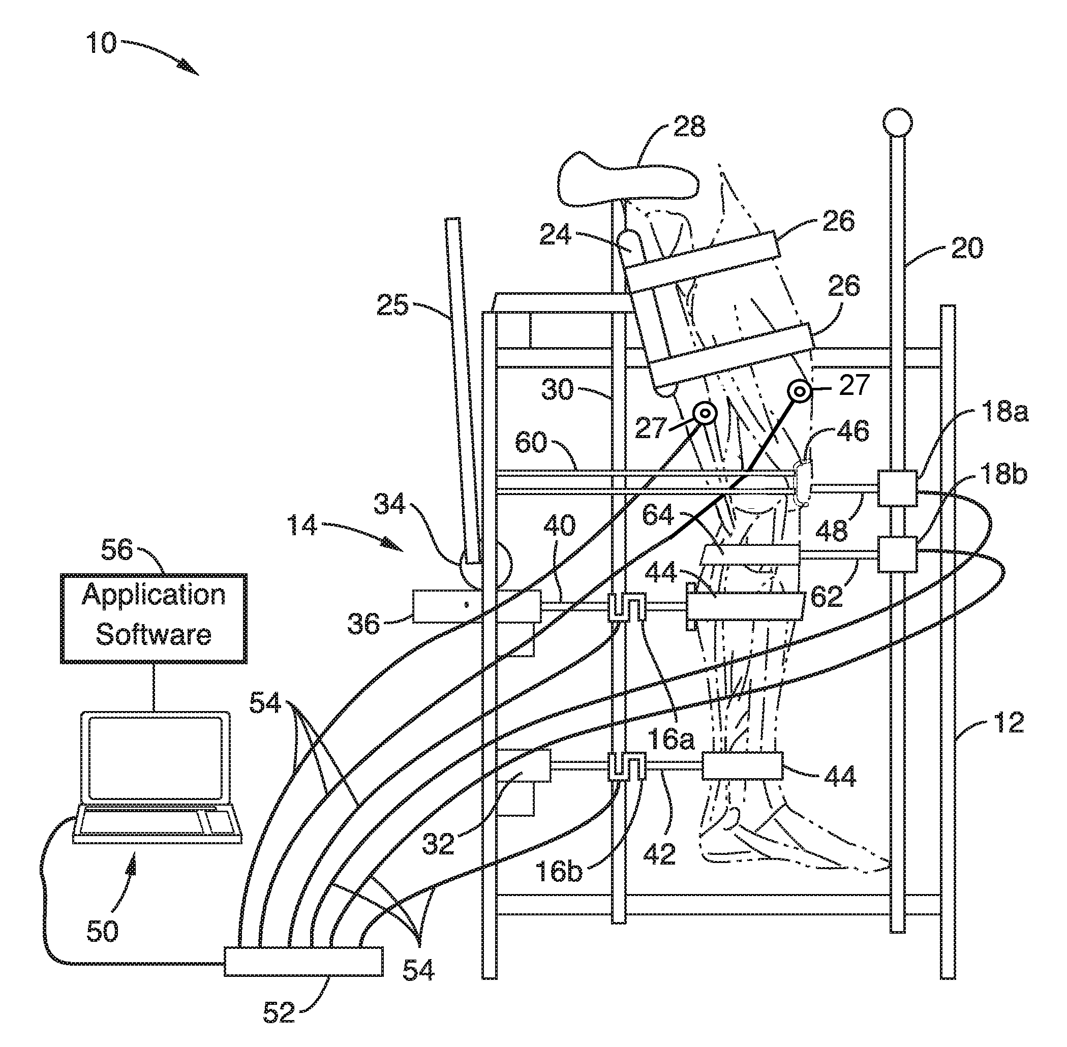
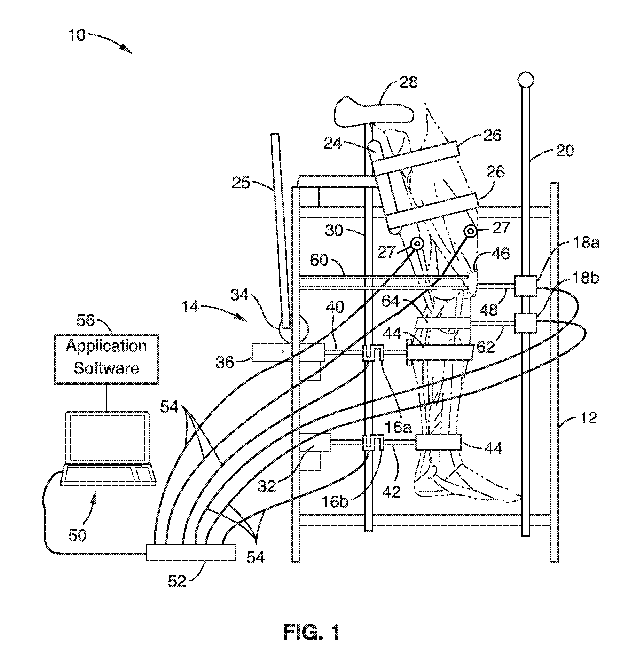
[0040]Measuring the anterior displacement of the tibia relative to the femur can be problematic due to how devices are attached to the body and forces applied, but the novel attachment system of knee arthrometer apparatus 10 eliminates many of these problems. It was found that the key to an accurate measurement was to provide a relatively constant force against the bone where the displacement measurements are made. The string potentiometers 18a, 18b provide a relatively constant retraction force. The force at the attachment location of potentiometer 18b (FIG. 1) remains relatively constant during any displacement of the lower leg, therefore giving reliable measures.

[0041]Tracking the displacement of the femur is more difficult. In a preferred configuration, patella loops were used that could encapsulate the patella, but be secured to the femur. It was found the attachment means of potentiometer 18a (FIG. 1) provides a relatively constant force on the femur that does not change durin...

example 2

[0044]We next tested the repeatability of the knee arthrometer apparatus 10 for making knee laxity measurements. Fifteen subjects were tested hourly for five hours and allowed only to work at a computer and take short walking breaks. Right knee laxity was determined each hour. ACL force-deformation curves resulting from two tests separated by an hour are illustrated in FIG. 3A and FIG. 3B, respectively. FIG. 3A and FIG. 3B show the estimated ACL force deformation profile during ˜20 anterior-posterior loading cycles for a subject tested at two different times. Similar profiles were obtained for each test. The average knee laxity within each subject varied by less than 0.5 mm and showed no trend. The above results confirm that the knee arthrometer apparatus 10 of the present description can reliably measure knee laxity to within 0.5 mm.

example 3

[0045]The knee arthrometer apparatus 10 was also used to acquire preliminary data pertaining to the specific theory that repeated bouts of strenuous exercise can lead to laxity changes in the knee, reflective of structural alterations (i.e. damage) in the ACL. Before presenting results from these tests, a brief description of the rationale supporting overuse mechanisms of catastrophic ACL injury is warranted.

[0046]The basic mechanisms of ACL injuries incurred during non-contact movement that a person has performed many times previously without incident are not understood, but there is evidence supporting overuse mechanisms, e.g. that micro-trauma, or selective fiber disruption, of the human ACL may be caused by a rapid increase in training load, frequency, and / or duration. A ligament may be able to heal certain levels of micro-damage if given sufficient recovery time. However, if strenuous activity occurs at a frequency that creates micro-damage faster than it can be repaired by the...


PUM


Abstract

Devices and methods are disclosed for quantifying temporal changes in human anterior cruciate ligament (ACL) structural properties, such as Anterior-Posterior tibial shear force (TSF) and Anterior-Posterior tibial shear displacement (TSD) for testing ACL overuse injury during training and minimizing or preventing ACL injury.

Description

CROSS-REFERENCE TO RELATED APPLICATIONS[0001]This application is a 35 U.S.C. §111(a) continuation of PCT international application number PCT / US2014 / 070936 filed on Dec. 17, 2014, incorporated herein by reference in its entirety, which claims priority to, and the benefit of, U.S. provisional patent application Ser. No. 61 / 916,927 filed on Dec. 17, 2013, incorporated herein by reference in its entirety. Priority is claimed to each of the foregoing applications.[0002]The above-referenced PCT international application was published as PCT International Publication No. WO 2015 / 095383 on Jun. 25, 2015, which publication is incorporated herein by reference in its entirety.STATEMENT REGARDING FEDERALLY SPONSORED RESEARCH OR DEVELOPMENT[0003]Not ApplicableINCORPORATION-BY-REFERENCE OF COMPUTER PROGRAM APPENDIX[0004]Not ApplicableNOTICE OF MATERIAL SUBJECT TO COPYRIGHT PROTECTION[0005]A portion of the material in this patent document is subject to copyright protection under the copyright law...

Claims


Application Information

Patent Timeline
IPC IPC(8): A61B5/00A61B5/11A61B5/0492A61B5/296
CPCA61B5/4585A61B5/0492A61B5/1121A61B2562/06A61B5/702A61B2562/0261A61B5/1126A61B5/389A61B5/296
Inventor HAWKINS, DAVID
Owner RGT UNIV OF CALIFORNIA
Why Eureka
Try Eureka