
Thermosetting composition with photo-alignment property, alignment layer, substrate with alignment layer, retardation plate, and device

Active Publication Date: 2016-12-08
DAI NIPPON PRINTING CO LTD
View PDF2 Cites 12 Cited by
  • Summary
  • Abstract
  • Description
  • Claims
  • Application Information

AI Technical Summary

Benefits of technology

This patent makes a thermosetting composition that can align itself very sensitive to light. This composition has good resistance to heat and solvents, and can be used to make alignment layers.

Problems solved by technology

For example, the alignment layer is occasionally exposed to heat and solvents in the production process of various kinds of devices, and to high temperature during the use of various kinds of devices.
The exposure of the alignment layer to high temperature brings a possibility of remarkably deteriorating liquid crystal alignment ability.

Method used


Image

  • Thermosetting composition with photo-alignment property, alignment layer, substrate with alignment layer, retardation plate, and device
  • Thermosetting composition with photo-alignment property, alignment layer, substrate with alignment layer, retardation plate, and device
  • Thermosetting composition with photo-alignment property, alignment layer, substrate with alignment layer, retardation plate, and device

Examples


first embodiment

(1) First Embodiment

[0225]The first embodiment of the liquid crystal display element in an embodiment of the present invention includes a first substrate with an alignment layer in which a first alignment layer is disposed on a first substrate, a second substrate with an alignment layer in which a second alignment layer is disposed on a second substrate, and a liquid crystal layer disposed between the first substrate with an alignment layer and the second substrate with an alignment layer, and the first alignment layer and the second alignment layer are such as to be formed from the thermosetting composition with a photo-alignment property, or the alignment layer described above.

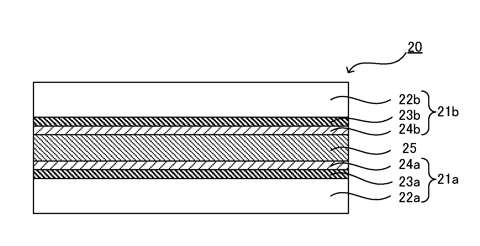
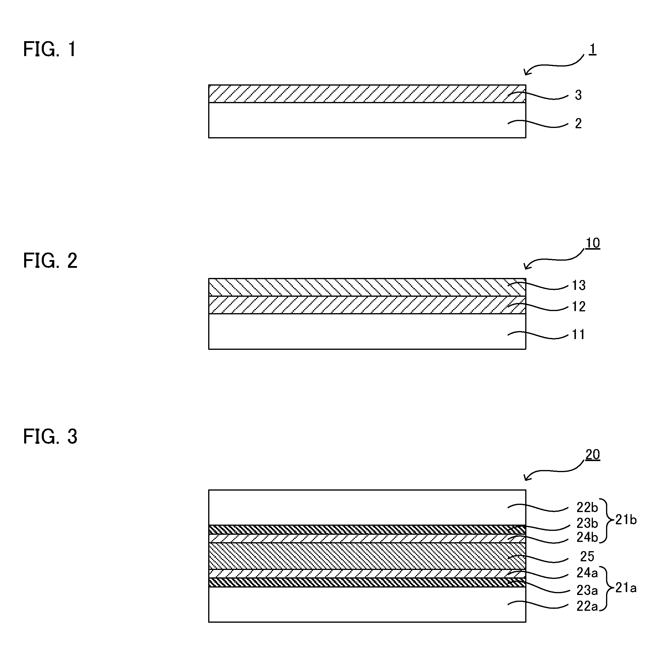
[0226]FIG. 3 is a schematic sectional view showing an example of the liquid crystal display element in an embodiment of the present invention. A liquid crystal display element 20 exemplified in FIG. 3 comprises a first substrate with an alignment layer 21a, a second substrate with an alignment layer 21b, and...

second embodiment

(2) Second Embodiment

[0231]The second embodiment of the liquid crystal display element in an embodiment of the present invention comprises the retardation plate.

[0232]The constitutions of the liquid crystal display element may be the same as the constitutions of a general liquid crystal display element. For example, the retardation plate may be disposed outside the substrate constituting the liquid crystal display element, or the substrate constituting the liquid crystal display element may also serve as the substrate constituting the retardation plate, and the alignment layer and the retardation layer may be disposed inside the substrate.

[0233]The present disclosure is not limited to the embodiments. The embodiments are exemplification, and any is included in the technical scope of the present disclosure if it has substantially the same constitution as the technical idea described in the claim of the present disclosure and offers similar operation and effect thereto.

examples

[0234]Embodiments of the present invention are described in further detail with reference to examples and comparative examples hereinafter.


PUM

PropertyMeasurementUnit
Structureaaaaaaaaaa

Abstract

An embodiment of the present invention provides a thermosetting composition with a photo-alignment property, including a copolymer containing a photo-alignment constitutional unit represented by the following formula (1) and a thermal cross-linking constitutional unit. In the formula (1), X represents a photo-alignment group causing a photo-isomerization reaction or a photo-dimerization reaction, L1 represents a single bond, —O—, —S—, —COO—, —COS—, —CO—, —OCO—, —OCO(CH2)nCOO—, —OCOCH2CH2OCH2CH2COO—, —OCOC6H4O—, —OCOC6H10O—, —COO(CH2)nO—, —COOC6H4O—, —COOC6H10O—, —O(CH2)nO—, —OC6H4O—, —OC6H10O—, or —(CH2)nO—, n represents 1 to 4, R1 represents a hydrogen atom or a monovalent organic group, and k represents 1 to 5.

Description

TECHNICAL FIELD[0001]The present invention relates to a thermosetting composition with a photo-alignment property, which is used for an alignment layer.BACKGROUND ART[0002]With regard to a liquid crystal, diverse applications to various kinds of optical elements such as a retardation plate and a polarizing plate except a liquid crystal display element have been studied by utilizing an alignment property and anisotropy of physical properties such as refractive index, dielectric constant and magnetic susceptibility.[0003]An alignment layer is used for aligning a liquid crystal. A rubbing method and a photo-alignment method are known as examples of a formation method for an alignment layer, and the photo-alignment method is useful in view of being capable of controlling quantitative alignment treatment by reason of no occurrence of static electricity and dust as a problem of the rubbing method (refer to Patent Document 1, for example).[0004]Thermal stability and solvent resistance exce...

Claims


Application Information

Patent Timeline
IPC IPC(8): C09K19/56C08F220/18G02B5/30C08F220/28G02F1/1337C08F220/68C08F212/14
CPCC09K19/56C08F220/68C08F220/18C08F212/145C08F2220/283C08F212/14G02F1/133711G02B5/3083C08F220/28C08F212/32C08F212/34C08F220/20C08F220/58C08F212/21C08F212/22C08F212/24C08F212/26C08F220/1808C08F220/282C08F220/325G02F1/13363G02F1/133788C08F12/24C08F12/26C08F12/32C08F12/34C08F220/283C08F12/22G02B5/30
Inventor MOTOOKA, MAMIOKUYAMA, KEN-ICHI
Owner DAI NIPPON PRINTING CO LTD
Features
  • Generate Ideas
  • Intellectual Property
  • Life Sciences
  • Materials
  • Tech Scout
  • Unparalleled Data Quality
  • Higher Quality Content
  • 60% Fewer Hallucinations
Learn More