Hydraulic control device and method for controlling the same

a control device and hydraulic technology, applied in the direction of gearing control, gearing element control, belt/chain/gearing, etc., can solve the problems of shifting shock, reducing the opening area of the port, and reducing the length of the regulating valv

Active Publication Date: 2016-12-08
JATCO LTD
View PDF0 Cites 2 Cited by
  • Summary
  • Abstract
  • Description
  • Claims
  • Application Information

AI Technical Summary

Benefits of technology

[0012]These aspects ensures restraining the shift shock due to the sudden change in the secondary pressure in the case where

Problems solved by technology

Especially, in the case of low oil temperature and high oil viscosity, an operation of the spool is slow and therefore time to remove a stuck state of the pressure regulating valve lengthens, failing to quickly increase the opening a

Method used


Image

  • Hydraulic control device and method for controlling the same
  • Hydraulic control device and method for controlling the same
  • Hydraulic control device and method for controlling the same

Examples


Embodiment Construction

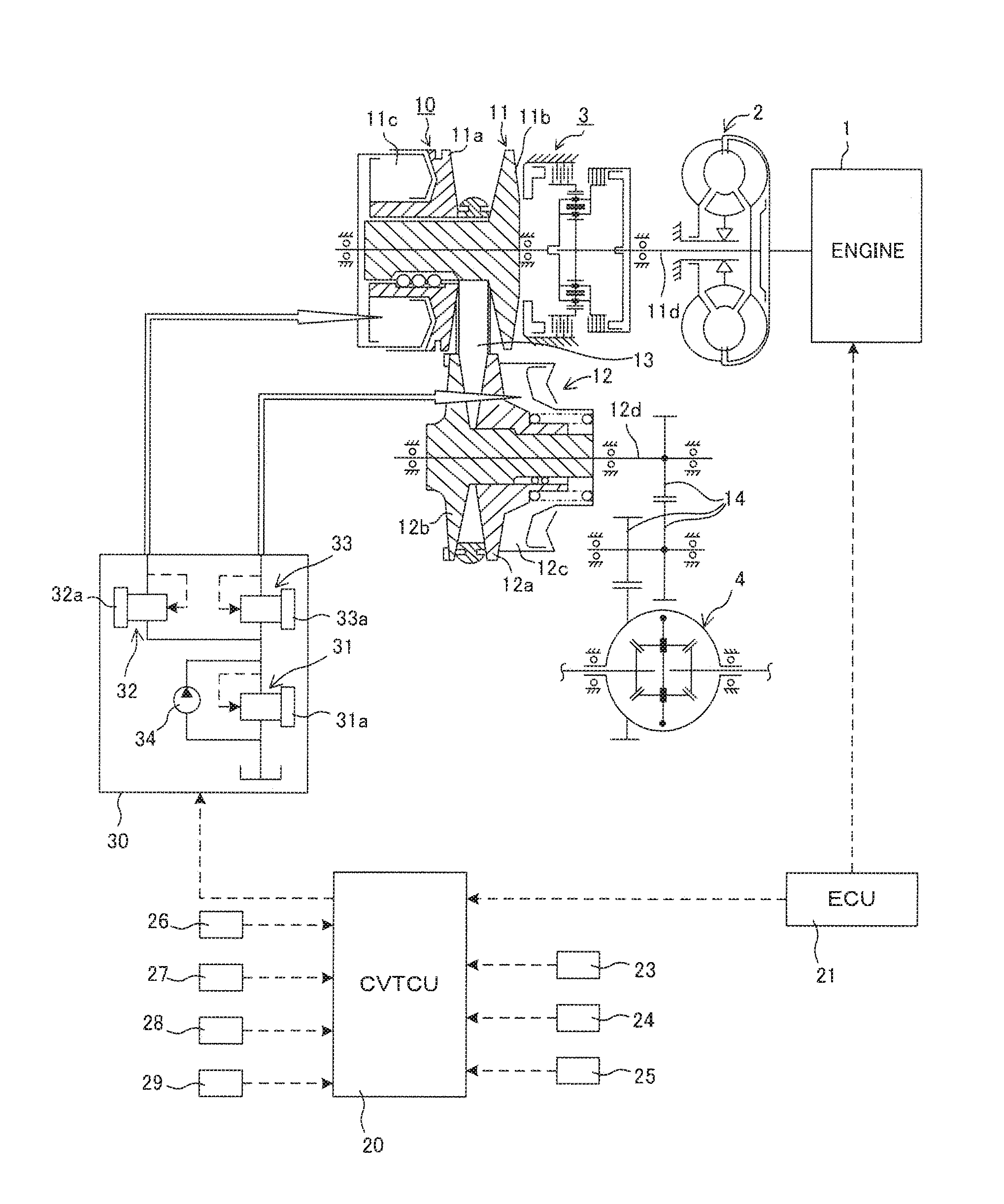
[0017]The following describes an embodiment of the present invention in detail with reference to the accompanying drawings and a similar description. FIG. 1 is a schematic configuration diagram illustrating a hydraulic control device of a belt-type continuously variable transmission 10 according to the embodiment. The belt-type continuously variable transmission (hereinafter referred to as a “continuously variable transmission”) 10 includes a primary pulley 11, a secondary pulley 12, a belt 13, a CVT control unit 20 (hereinafter referred to as a “CVTCU”), and a hydraulic control unit 30. The continuously variable transmission 10 is a both-pressure-regulating continuously variable transmission.

[0018]It should be noted that, a speed ratio of the continuously variable transmission 10 is a value found by dividing a rotation speed of the primary pulley 11 by a rotation speed of the secondary pulley 12. A large speed ratio is referred to as “Low,” and a small speed ratio is referred to as...


PUM


Abstract

A hydraulic control device controls hydraulic pressure supplied to a continuously variable transmission. The hydraulic control device includes a pressure regulating valve, a solenoid valve configured to control the pilot pressure, line pressure control means, and hydraulic control means. The pressure regulating valve includes an input port to which line pressure is input, an output port configured to supply an oil chamber of a second pulley with a second pulley pressure, a drain port configured to discharge the second pulley pressure from the oil chamber, and a spool moving according to pilot pressure to regulate the second pulley pressure. The line pressure control means is configured to control the line pressure on the basis of the second pulley pressure and first pulley pressure of first pulley. The hydraulic control means is configured to temporarily change the pilot pressure from set pressure to configure the line pressure identical to the second pulley pressure.

Description

TECHNICAL FIELD[0001]The present invention relates to a hydraulic control device.BACKGROUND ART[0002]JP2001-235013A discloses a hydraulic control device for vehicle automatic transmission that prevents a hydraulic lock in a signal pressure oil passage at a low temperature to improve responsiveness of a hydraulic control valve.[0003]In JP2001-235013A, a hydraulic-lock-preventing oil passage is disposed. The hydraulic-lock-preventing oil passage drains a part of signal pressure to a signal pressure oil passage, which supplies signal pressure from a linear solenoid valve to a signal oil chamber in a hydraulic control valve. This ensures preventing the hydraulic lock and a quick communication between an output port and a drain port.SUMMARY OF INVENTION[0004]With a both-pressure-regulating type continuously variable transmission that regulates primary pressure and secondary pressure with line pressure as source pressure and that can reduce the line pressure, discharge pressure of an oil ...

Claims


Application Information

Patent Timeline
IPC IPC(8): F16H61/662
CPCF16H61/66272F16H61/0021
Inventor HASHIMOTO, YASUYUKITAKAHASHI, SEIICHIROHONMA, TOMOAKIKABE, TOMOAKIMORIFUJI, NOBUHIKOKATO, NOBUHIDEGOKA, HITOSHISUGITA, KOICHI
Owner JATCO LTD
Why Eureka
Try Eureka