Heat exchange apparatus of vehicle

a technology of heat exchange apparatus and vehicle, which is applied in the direction of mechanical apparatus, machines/engines, engine components, etc., can solve the problems of inability of the coolant to appropriately cool the time required to complete the warming of the oil cooler and the atf warmer, and the inability to warm the atf and the engine oil. to achieve the effect of reducing the time required to complete the warming of the oil cooler and the atf warmer, and reducing the heat capacity

Inactive Publication Date: 2016-12-15
TOYOTA JIDOSHA KK
View PDF16 Cites 6 Cited by
  • Summary
  • Abstract
  • Description
  • Claims
  • Application Information

AI Technical Summary

Benefits of technology

[0015]Because the EGR valve has a smaller heat capacity than the oil cooler, the engine oil, the ATF warmer, and the ATF, the EGR valve is promptly warmed before completion of warming by the oil cooler and the ATF warmer. Thus, the heat that the coolant has received from the exhaust gas in the valve heat exchange section can be used for warming by the oil cooler and warming by the ATF warmer. Therefore, the time required to complete warming by the oil cooler and the ATF warmer can further be reduced.

Problems solved by technology

Meanwhile, there is a case where long time is required to warm the automatic transmission through heating of the ATF in the ATF warmer and to warm each component to which the engine oil is supplied through heating of the engine oil in the oil cooler.
Thus, heat of the coolant that has passed through the EGR cooler cannot be used for warming by the oil cooler and the ATF warmer.
Therefore, incapability of the coolant to appropriately cool the ATF and the engine oil can be inhibited.

Method used


Image

  • Heat exchange apparatus of vehicle
  • Heat exchange apparatus of vehicle
  • Heat exchange apparatus of vehicle

Examples


Embodiment Construction

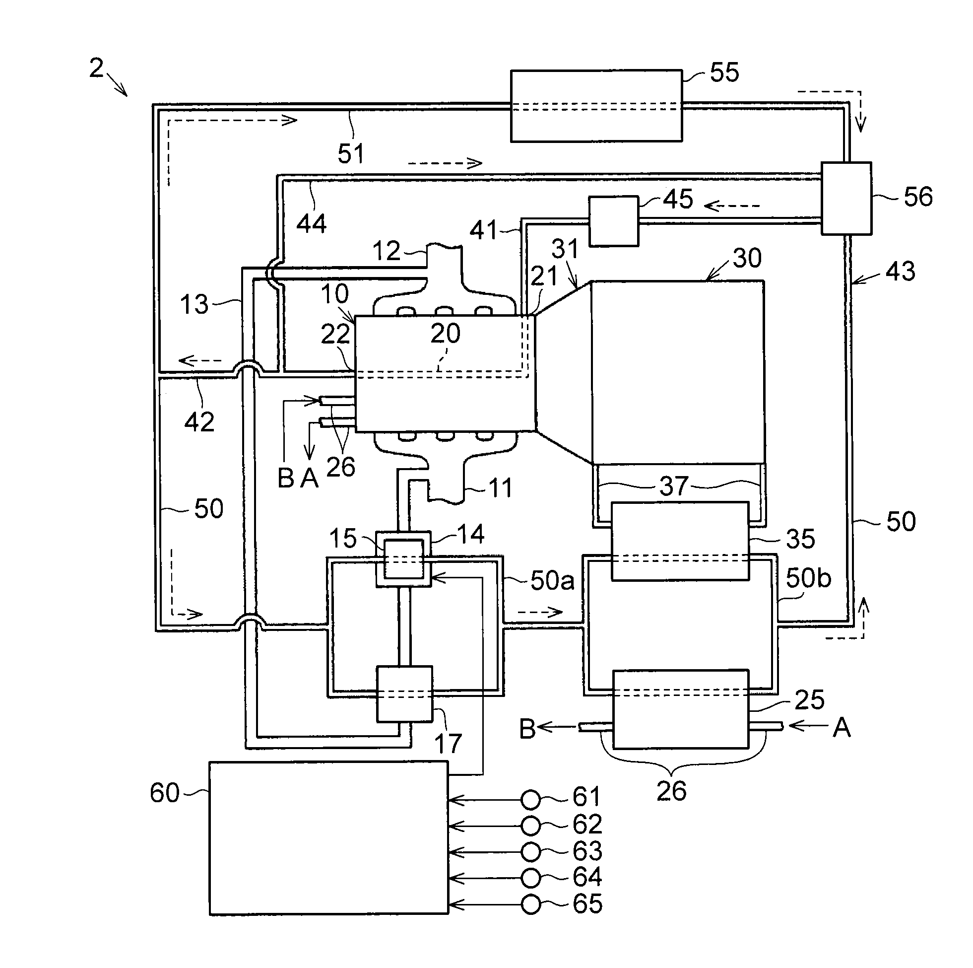
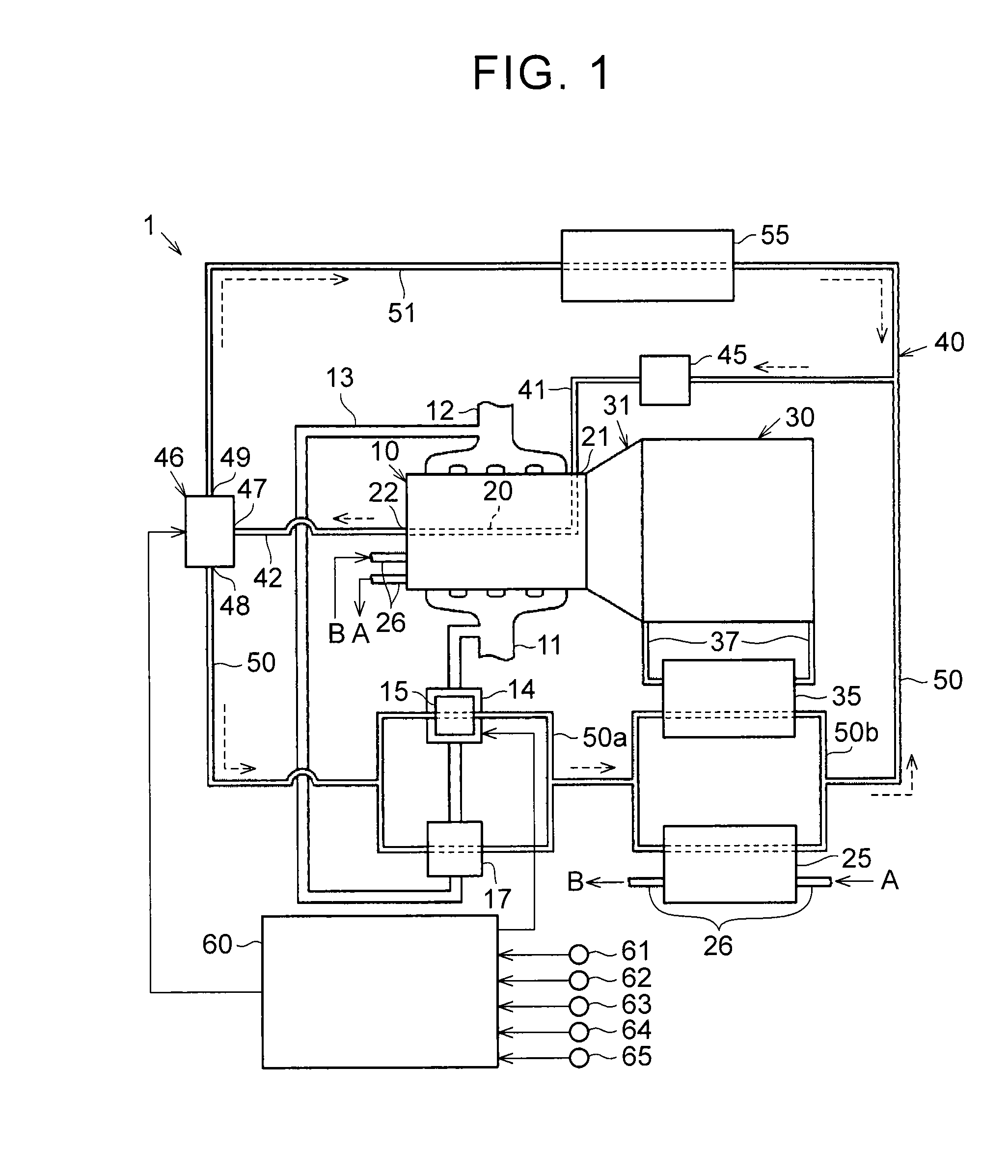
[0025]A description will hereinafter be made on a first embodiment in which a heat exchange apparatus of a vehicle is embodied with reference to FIG. 1 to FIG. 4. An internal combustion engine 10 and an automatic transmission 30 are mounted in the vehicle of this embodiment.

[0026]The internal combustion engine 10 of this embodiment is a gasoline engine. The internal combustion engine 10 includes an intake passage 11 and an exhaust passage 12. The intake passage 11 is configured to feed air into a combustion chamber. The exhaust passage 12 is configured to discharge combustion gas combusted in the combustion chamber as exhaust gas. An EGR passage 13 for recirculating the exhaust gas that flows through the exhaust passage 12 to the intake passage 11 is connected to the intake passage 11 and the exhaust passage 12. The EGR passage 13 is provided with an EGR valve 14 for adjusting a recirculation amount of the exhaust gas. In this embodiment, a valve heat exchange section 15 for heat ex...


PUM


Abstract

A heat exchange apparatus of a vehicle includes a coolant circuit, to which a water pump, an EGR cooler in which exhaust gas flowing through an EGR passage and a coolant exchange heat, an oil cooler in which engine oil and the coolant exchange heat, and an ATF warmer in which an automatic transmission fluid as a hydraulic fluid of an automatic transmission and the coolant exchange heat are connected, between a water jacket exit and a water jacket entry of an internal combustion engine. In the coolant circuit, the oil cooler and the ATF warmer are connected to a downstream side of the EGR cooler.

Description

INCORPORATION BY REFERENCE[0001]The disclosure of Japanese Patent Application No. 2015-116693 filed on Jun. 9, 2015 including the specification, drawings and abstract is incorporated herein by reference in its entirety.BACKGROUND[0002]1. Technical Field[0003]The present disclosure relates to a heat exchange apparatus of a vehicle.[0004]2. Description of Related Art[0005]In Japanese patent application publication No. 2014-196708 (JP 2014-196708 A), a heat exchange apparatus of a vehicle that includes a coolant circuit in which an oil cooler and an air-conditioning heater are connected in parallel between an exit of a water jacket of an internal combustion engine and an entry of the water jacket is disclosed.SUMMARY[0006]In heat exchangers connected in parallel between the exit of the water jacket of the internal combustion engine and the entry of the water jacket as in the coolant circuit, for example, an EGR cooler, an oil cooler, and an ATF warmer might be connected in parallel bet...

Claims


Application Information

Patent Timeline
Patent Type & Authority Applications(United States)
IPC IPC(8): F01P11/08F02M26/30F02M26/28
CPCF01P11/08F02M26/30F02M26/28F01P3/20F01P2037/02F01P2060/045F01P2060/16Y02T10/12
Inventor KAWAMOTO, NAOYA
Owner TOYOTA JIDOSHA KK
Why Eureka
Try Eureka