Liquid column-based capacitive sensors

a capacitive sensor and liquid column technology, applied in the field of sensing devices, can solve the problems of insufficient pressure sensitivity and resolution, one or more shortcomings of existing microfluidic sensors, etc., and achieve the effects of high sensitivity, simple fabrication, and excellent flexibility

Inactive Publication Date: 2016-12-15
RGT UNIV OF CALIFORNIA
View PDF1 Cites 32 Cited by
  • Summary
  • Abstract
  • Description
  • Claims
  • Application Information

AI Technical Summary

Benefits of technology

[0009]Microfluidic-based sensors have been an active area of research for their excellent flexibility, high sensitivity, simple fabrication, and wide adaptability. A variety of sensing and actuation mechanisms have been incorporated in the development of microfluidic sen

Problems solved by technology

However, the existing microfluidic sensors suffer from one or more shortcomings, such as being

Method used


Image

  • Liquid column-based capacitive sensors
  • Liquid column-based capacitive sensors
  • Liquid column-based capacitive sensors

Examples


example

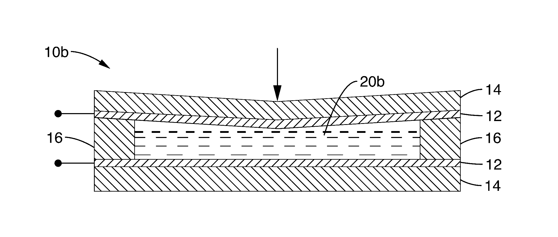
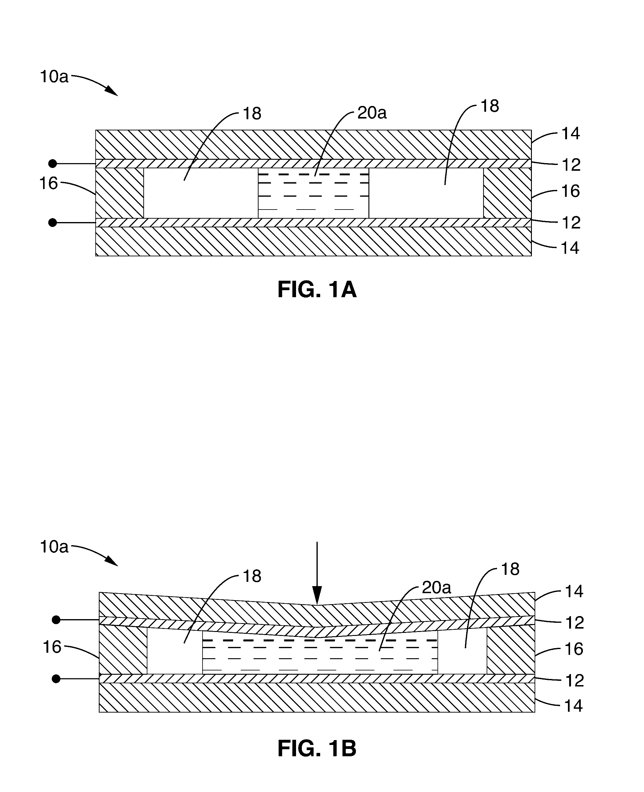
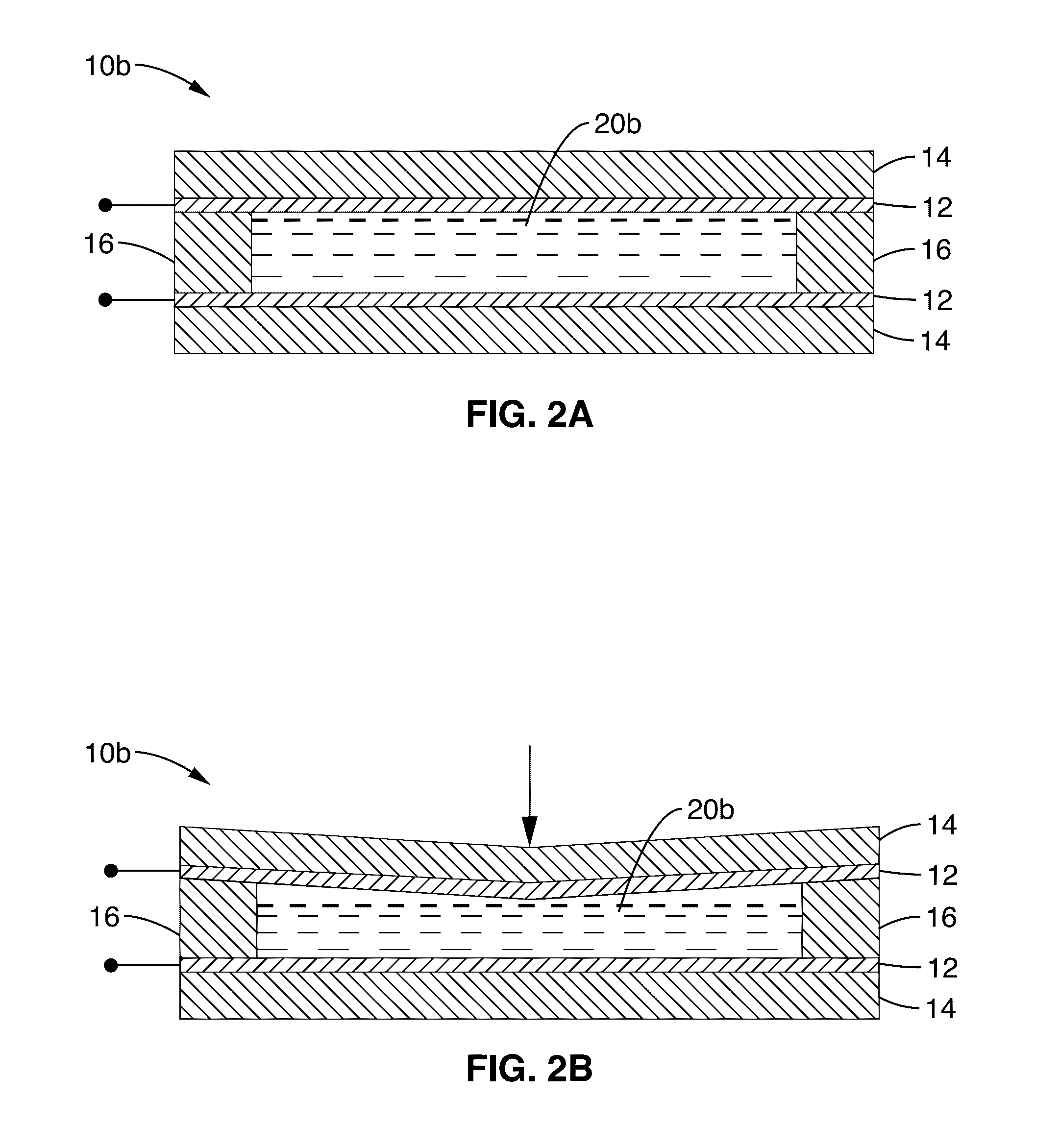
[0119]Experimental investigations of the sensing device of the present disclosure were conducted on individual sensing units of the iontronic microdroplet array. A measurement stage comprising of a force gauge with 1 mN resolution mounted on a computer-controlled step motor with a spatial resolution of 400 nm was used for simultaneously controlling and monitoring mechanical loads and displacements. Pressure values were calculated based on the ratio of the applied force to the surface area of the membrane in each sensing unit. The corresponding capacitive changes were directly recorded through an LCR meter. Each sensitivity measurement was conducted twice on two identical sensing devices. In the characterization of the responsive time, an electromagnetically driven pin actuator, powered by a pulsed voltage signal from 1 Hz to 100 Hz, was used to apply the periodic contact pressure to the sensor surface. The output signals of the IMA device are measured by use of the readout circuitry...


PUM


Abstract

A liquid column-based normal/shear pressure/force sensing device having an elastic electrolyte-electrode contact with large interfacial capacitance to achieve high sensitivity and resolution with flexible and transparent constructs.

Description

CROSS-REFERENCE TO RELATED APPLICATIONS[0001]This application is a 35 U.S.C. §111(a) continuation of PCT international application number PCT / US2014 / 070187 filed on Dec. 14, 2014, incorporated herein by reference in its entirety, which claims priority to, and the benefit of, U.S. provisional patent application Ser. No. 61 / 916,196 filed on Dec. 14, 2013, incorporated herein by reference in its entirety. Priority is claimed to each of the foregoing applications.[0002]The above-referenced PCT international application was published as PCT International Publication No. WO 2015 / 089491 on Jun. 18, 2015, which publication is incorporated herein by reference in its entirety.STATEMENT REGARDING FEDERALLY SPONSORED RESEARCH OR DEVELOPMENT[0003]This invention was made with Government support under ECCS-0846502 and ECCS-1307831, awarded by the National Science Foundation. The Government has certain rights in the invention.INCORPORATION-BY-REFERENCE OF COMPUTER PROGRAM APPENDIX[0004]Not Applicab...

Claims


Application Information

Patent Timeline
IPC IPC(8): H01G11/08A61B5/021G01L1/14
CPCH01G11/08A61B2562/0247A61B5/021G01L1/142A61B2562/0217G01L1/02H01G5/0132H01G5/38
Inventor PAN, TINGRUINIE, BAOQINGLI, RUYABRANDT, JAMES D.
Owner RGT UNIV OF CALIFORNIA
Why Eureka
Try Eureka