Substrate processing apparatus

a technology of substrate and processing equipment, which is applied in the direction of furnaces, furnace safety devices, furnace types, etc., can solve the problems of reducing the yield rate of device manufacturing, and achieve the effect of suppressing the reduction of the yield rate caused by particles in the processing furna

Inactive Publication Date: 2016-12-15
KOKUSA ELECTRIC CO LTD
View PDF8 Cites 15 Cited by
  • Summary
  • Abstract
  • Description
  • Claims
  • Application Information

AI Technical Summary

Benefits of technology

[0007]According to the present invention, conditions in a processing furnace can be monitored and a

Problems solved by technology

Due to particles occurring along with these processes, degradation in film quality, lot rejec

Method used


Image

  • Substrate processing apparatus
  • Substrate processing apparatus
  • Substrate processing apparatus

Examples


first embodiment

[0061]Next, the installation position of a particle measurement opening 400 will be described in detail using FIGS. 5 and 6a and 6b.

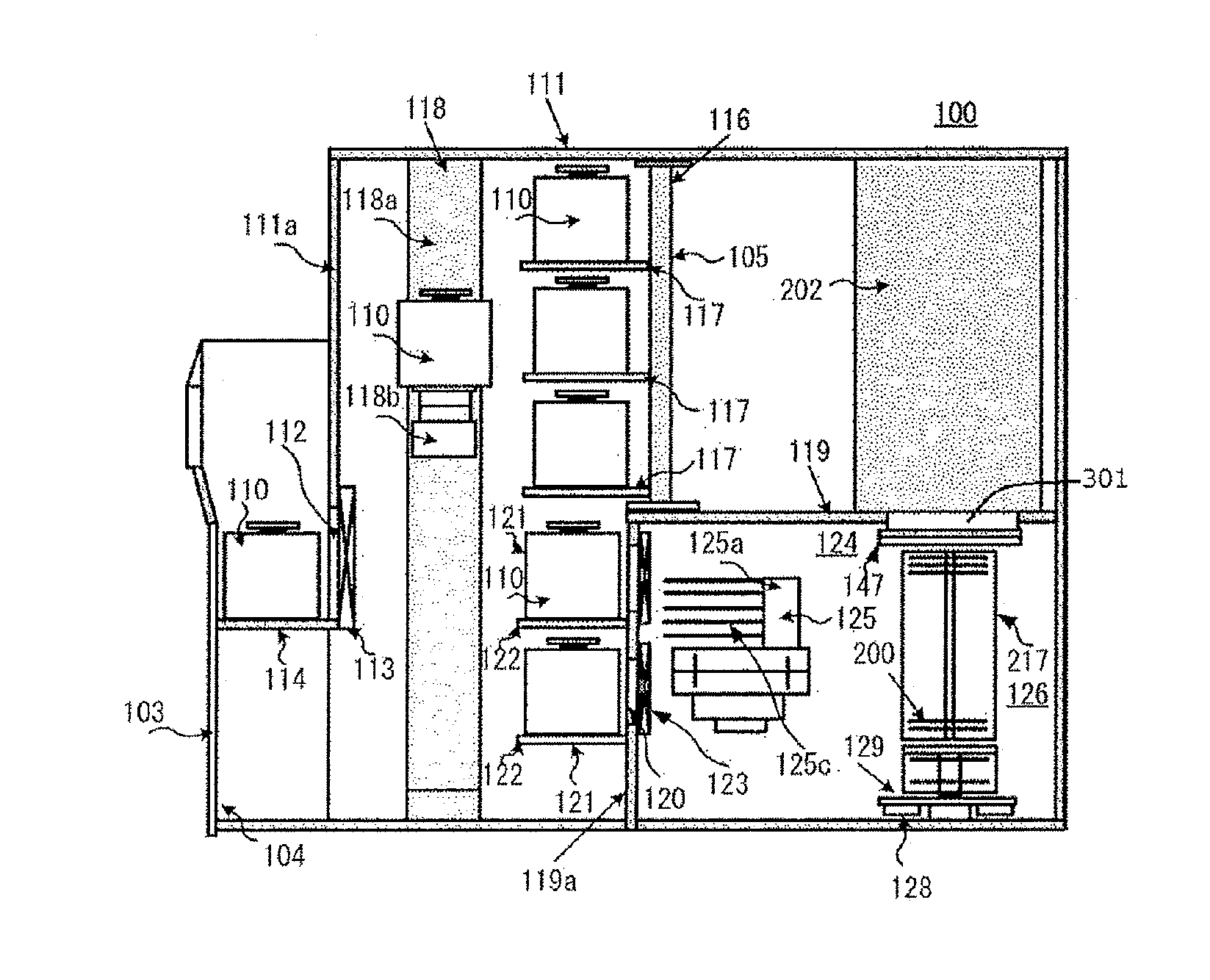
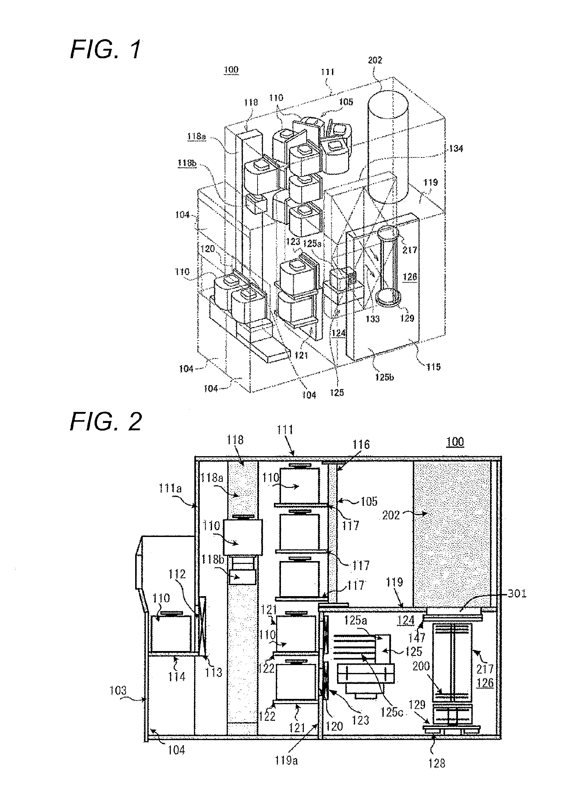
[0062]In a transfer chamber 124, in order to maintain a clean environment, a clean unit 134 equipped with an air filter is installed and the atmosphere in the transfer chamber 124 is circulated. FIG. 6a illustrates a case in which a clean unit 134 is installed on a side surface of a transfer chamber 124, and FIG. 6b illustrates a case in which a clean unit 134 is installed at a corner portion of a transfer chamber 124. In order to efficiently capture particles in a processing furnace 202 coming out of a furnace opening 301 when a boat 217 is unloaded and the furnace opening 301 is opened after substrate processing, a particle measurement opening 400 is installed at a position on the opposite side of the boat 217 from the clean unit 134, preferably, a position where the air flow of clean air 133 from the clean unit 134 is in line with a furnace opening ...

second embodiment

[0064]Next, the installation position of a particle measurement opening 400 will be described using FIGS. 7a, 7b, and 7c. In the present embodiment, a substrate processing apparatus 100 is configured to include two transfer chambers 124.

[0065]In each transfer chamber 124, in order to maintain a clean environment, a clean unit 134 equipped with an air filter is installed and the gas in the transfer chamber 124 is circulated. FIGS. 7a and 7c illustrate a case in which the clean unit 134 is installed on a side surface of each transfer chamber 124, and FIG. 7b illustrates a case in which the clean unit 134 is installed at a corner portion of each transfer chamber 124. As in the first embodiment, in the second embodiment, too, in order to efficiently capture particles coming out of a furnace opening 301, a particle measurement opening 400 is installed at a position on the opposite side of a boat 217 from the clean unit 134, preferably, a position facing the clean unit 134 with the boat 2...


PUM


Abstract

The present invention provides a technique in which a reduction in yield rate caused by particles occurring in the processing furnace is suppressed. The technique includes a substrate processing apparatus comprising a transfer chamber including a gas supply mechanism on a side surface thereof and configured to transfer a substrate to a substrate holder, a processing furnace, a furnace opening, a cap having the substrate holder placed thereon and configured to close the furnace opening, a raising/lowering mechanism configured to raise and lower the cap, a measurer installed at a position facing the gas supply mechanism in the transfer chamber with the substrate holder interposed therebetween, and configured to count a number of particles at the furnace opening, and a control unit configured to control the raising/lowering mechanism and the measurer so as to start measurement of a number of particles by the measurer when the furnace opening is opened.

Description

TECHNICAL FIELD[0001]The present invention relates to a substrate processing apparatus.RELATED ART[0002]In general, in a substrate processing apparatus which is used in a semiconductor device manufacturing process, annealing and film formation are performed using processing gas, etc., in a processing furnace where wafers (substrates) are processed. Due to particles occurring along with these processes, degradation in film quality, lot rejection, etc., occur, causing a program of a reduction in the yield rate of device manufacturing. For a technique for suppressing such particles, there is, for example, a technique described in Patent Literature 1.CITATION LISTPatent Literature[0003]Patent Literature 1: JP 2012-79907 ASUMMARY OF INVENTIONTechnical Problem[0004]In the technique described in Patent Literature 1, however, although particles in a transfer chamber can be suppressed by purging the inside of the transfer chamber, when a large amount of particles occur in a processing furnac...

Claims


Application Information

Patent Timeline
IPC IPC(8): H01L21/67H01L21/677F27D21/00H01L21/673
CPCH01L21/67288H01L21/67109H01L21/67389F27D2021/0078H01L21/67772H01L21/67766F27D21/00H01L21/67778F27B17/0025H01L21/67017H01L21/67253H01L21/67769
Inventor TOKUNOBU, AKAOTANIYAMA, TOMOSHI
Owner KOKUSA ELECTRIC CO LTD
Why Eureka
Try Eureka