Shared-aperture antenna and base station

Active Publication Date: 2016-12-15
HUAWEI TECH CO LTD
View PDF5 Cites 25 Cited by
  • Summary
  • Abstract
  • Description
  • Claims
  • Application Information

AI Technical Summary

Benefits of technology

[0019]The embodiments of the present application provide a shared-aperture antenna and a base station, where the shared-aperture antenna includes a dielectric substrate, a microstrip antenna array, and an electrically small antenna array, where the microstrip antenna array includes rows of microstrip patch antenna units uniformly distributed in arrays, and the microstrip patch antenna units fit a surfac

Problems solved by technology

However, in a lot of communications devices, because of a requirement on integration and miniaturization of the communications devices, there is no sufficient space allocated to antennas of two or more different bands.
However, this solution does not resolve a problem of sharing an aperture between antenna arrays working in different bands. FIG. 2 shows tha

Method used


Image

  • Shared-aperture antenna and base station
  • Shared-aperture antenna and base station
  • Shared-aperture antenna and base station

Examples


embodiment 1

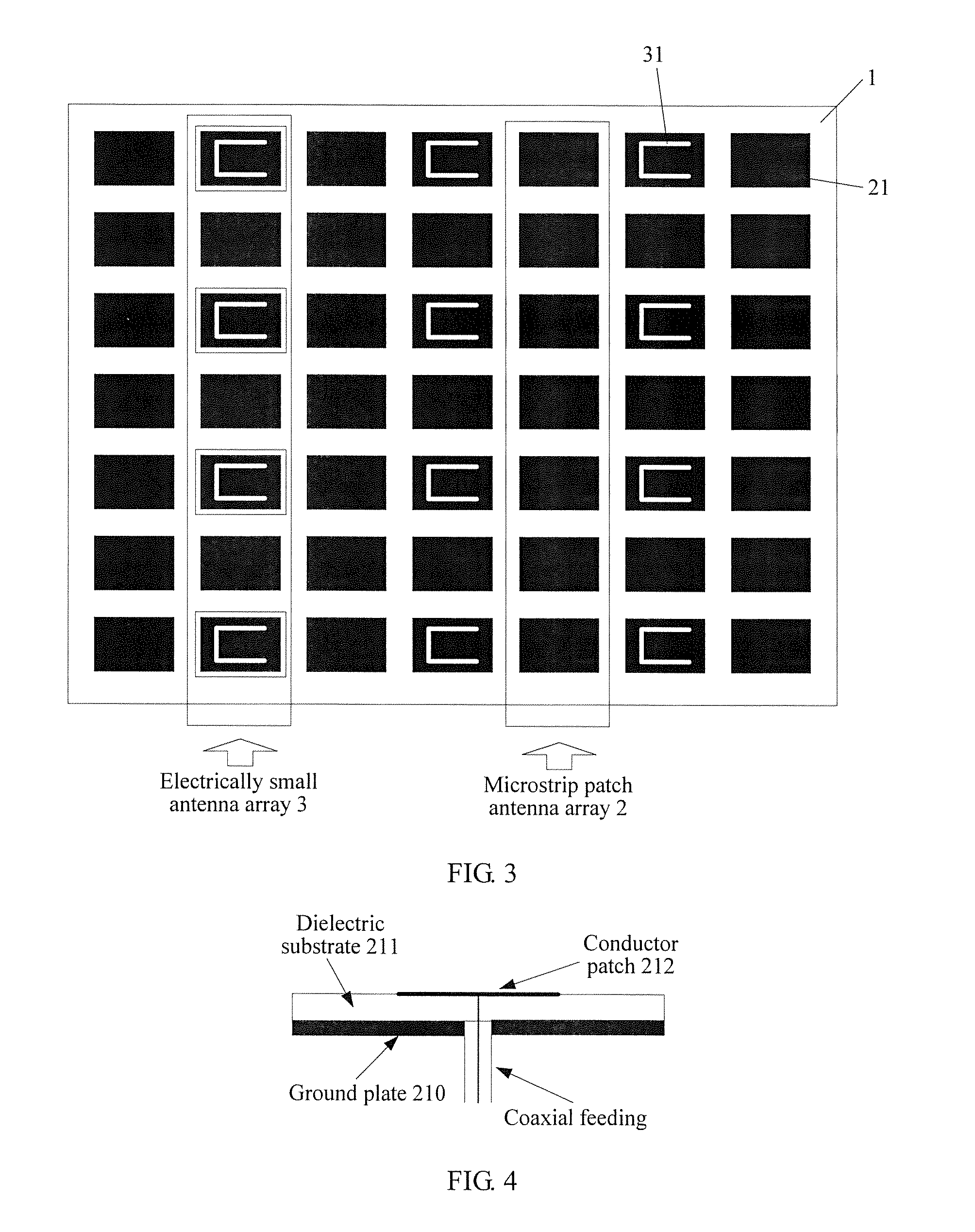
[0032]An embodiment of the present application provides a shared-aperture antenna. As shown in FIG. 3, the shared-aperture antenna includes: a dielectric substrate 1, a microstrip antenna array 2, and an electrically small antenna array 3, wherein:

[0033]the microstrip antenna array 2 includes rows of microstrip patch antenna units 21 uniformly distributed in arrays, and the microstrip patch antenna units 21 fit a surface of the dielectric substrate 1; and

[0034]the electrically small antenna array 3 includes electrically small antenna units 31 that are parallel to each other, and the electrically small antenna units 31 are inserted at intervals between the microstrip patch antenna units 21, and fit the surface of the dielectric substrate 1.

[0035]A part shown in black in FIG. 3 is the microstrip patch antenna unit 21, and a part shown in black and having a U-shaped slot is the electrically small antenna unit 31.

[0036]Specifically, as shown in FIG. 4, the microstrip patch antenna unit ...

embodiment 2

[0061]An embodiment of the present application provides a base station, where the base station includes: a signal processing device and a shared-aperture antenna, where

[0062]the shared-aperture antenna is configured to transmit and receive a wireless signal; and

[0063]the signal processing device is configured to receive and process the wireless signal received by the shared-aperture antenna, and transmit the processed signal by using the shared-aperture antenna.

[0064]Specifically, as shown in FIG. 3, the shared-aperture antenna includes a dielectric substrate 1, a microstrip antenna array 2, and an electrically small antenna array 3, where the microstrip antenna array 2 includes rows of microstrip patch antenna units 21 uniformly distributed in arrays, and the microstrip patch antenna units 21 fit a surface of the dielectric substrate 1. The electrically small antenna array 3 includes electrically small antenna units 31 that are parallel to each other; and the electrically small ant...


PUM


Abstract

The present application relates to the field of antenna technologies, and discloses a shared-aperture antenna and a base station, to resolve a problem of sharing an aperture between antenna arrays working in different frequency bands. The shared-aperture antenna includes a dielectric substrate, a microstrip antenna array, and an electrically small antenna array, where the microstrip antenna array includes rows of microstrip patch antenna units uniformly distributed in arrays, and the microstrip patch antenna units fit a surface of the dielectric substrate; the electrically small antenna array includes electrically small antenna units that are parallel to each other; and the electrically small antenna units are inserted at intervals between the microstrip patch antenna units, and fit the surface of the dielectric substrate.

Description

CROSS-REFERENCE TO RELATED APPLICATIONS[0001]This application is a continuation of International Application No. PCT / CN2014 / 072634, filed on Feb. 27, 2014, which is hereby incorporated by reference in its entirety.TECHNICAL FIELD[0002]The present application relates to the field of antenna technologies, and in particular, to a shared-aperture antenna and a base station.BACKGROUND[0003]With rapid development of wireless communications, a set of communications system needs to be capable of radiating and receiving multiple bands, so that an antenna matching the communications system needs to radiate and receive the multiple different bands. However, in a lot of communications devices, because of a requirement on integration and miniaturization of the communications devices, there is no sufficient space allocated to antennas of two or more different bands.[0004]To implement integrated design of antennas of different bands in limited space, the antennas of the different bands need to be ...

Claims


Application Information

Patent Timeline
IPC IPC(8): H01Q21/06H01Q5/42H01Q1/24
CPCH01Q21/065H01Q5/42H01Q1/246H01Q5/371H01Q9/0421H01Q21/205H01Q25/00H01Q5/30
Inventor DU, MINGDESHUAI, SONGLIN
Owner HUAWEI TECH CO LTD
Why Eureka
Try Eureka