
Microfluid device and three-dimensional microculture method for cell

a microfluidic device and cell technology, applied in cell culture active agents, biochemistry apparatus and processes, sterilization of apparatus, etc., can solve the problems of inability to express original function, difficulty in realizing a 3d cell culture technique, and small environment, and achieve high throughput and contribute to the commercial viability of mammal pluripotent stem cells.

Active Publication Date: 2016-12-22
KYOTO UNIV +1
View PDF0 Cites 3 Cited by
  • Summary
  • Abstract
  • Description
  • Claims
  • Application Information

AI Technical Summary

Benefits of technology

The present invention provides a microfluidic device that allows for the 3D culture of cells, including pluripotent stem cells, using a small amount of cells. The device can supply various physiologically active substances to a 3D gel while forming concentration gradients, which makes it possible to screen various substances for their effect on cell differentiation and functional regulation. This information is crucial for advancing tissue engineering, cell transplant therapy, or regenerative medicine. The device can also be used for drug discovery screening, as it enables a 3D culture that more accurately describes cell response to medicinal substances. The extracellular microenvironment is important for the formation and research of cancer stem cells, and the 3D culture method of the invention can contribute to the development of a basic remedy for cancer.

Problems solved by technology

However, the regulation occurs in an extremely small environment on a micrometer scale, and the traditional experimental cell culture technique using a 2D environment in a culture dish or a plate cannot reproduce the small environment.
Thus, there is a demand for a technique for creating an experimental 3D cell culture environment, which has been difficult to realize.
However, cells are present in a 3D environment in ordinary circumstances, and cannot express the original function in the 2D environment.
It has been difficult for traditional techniques to regulate these factors.
As a matter of course, it has been almost impossible to exhaustively analyze these factors.

Method used


Image

  • Microfluid device and three-dimensional microculture method for cell
  • Microfluid device and three-dimensional microculture method for cell
  • Microfluid device and three-dimensional microculture method for cell

Examples


example 1

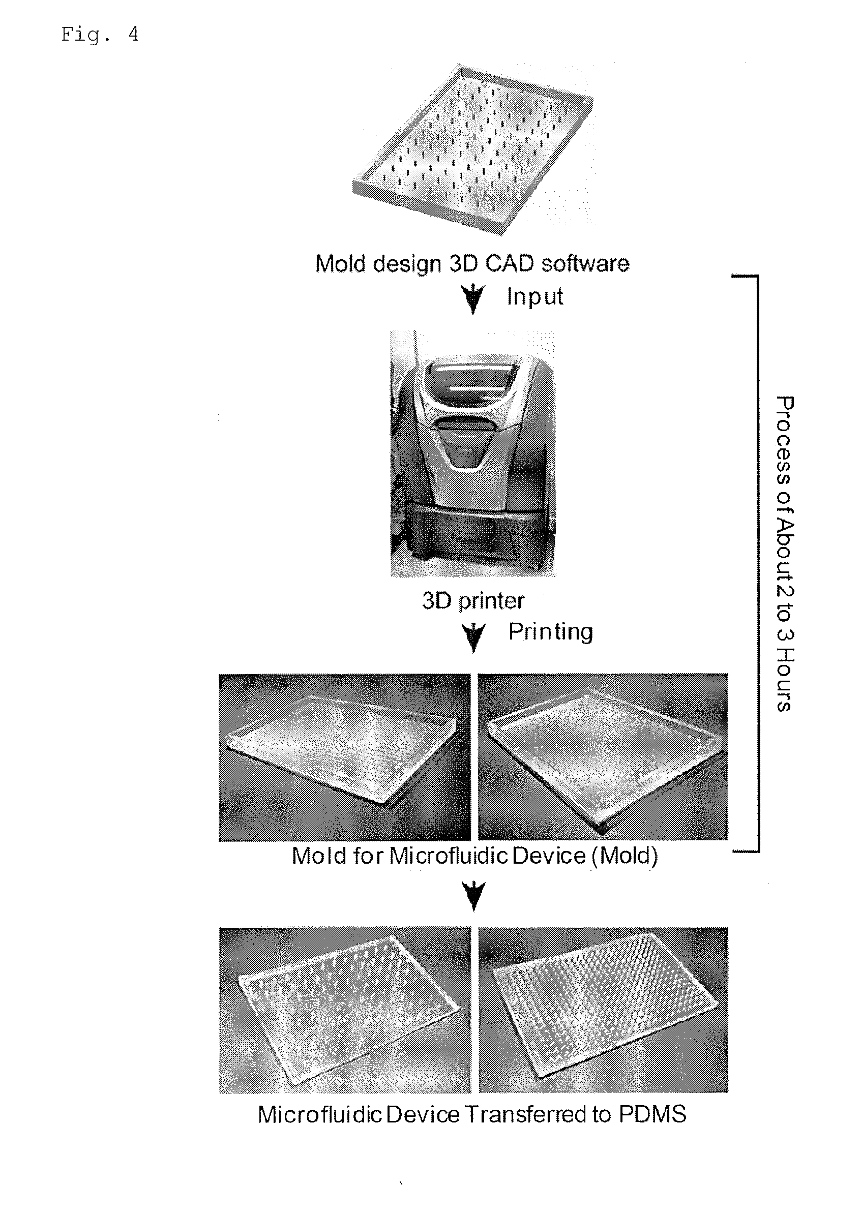
Method for Producing a Microfluidic Device Using a 3D Printer

(1) Materials

[0089]SYLGARD® 184 Silicone Elastomer kit (base, curing agent) (Dow Corning)

Nunc OmniTray (Thermo scientific 165218)

Glass Bottom Dish (Iwaki Glass Co. Ltd.)

3D Printer AGILISTA (Keyence)

Desiccator

[0090]Corona Fit CFG-500 (Shinko Electric & Instrumentation Co., Ltd.) 3D-CAD (AutoCAD, Blender, and others)

(2) Operation Procedure

Preparation of Mold

[0091]1. A mask of a mold design, which will be a mold for the microchannel structure, is prepared by using 3D image graphics software (3D-CAD).

2. The mold design is converted into an stf file.

3. The stf file is transferred to the 3D printer and printed.

Preparation of PDMS with a Microchannel Structure

1. A silicone elastomer base is mixed with a curing agent in a ratio of 10:1 (weight ratio) using a stirrer (PDMS mixture).

2. The PDMS mixture is poured into the mold printed by the 3D printer.

3. Degasification is performed with a desiccator for 30 minutes.

4. Heating is perf...

example 2

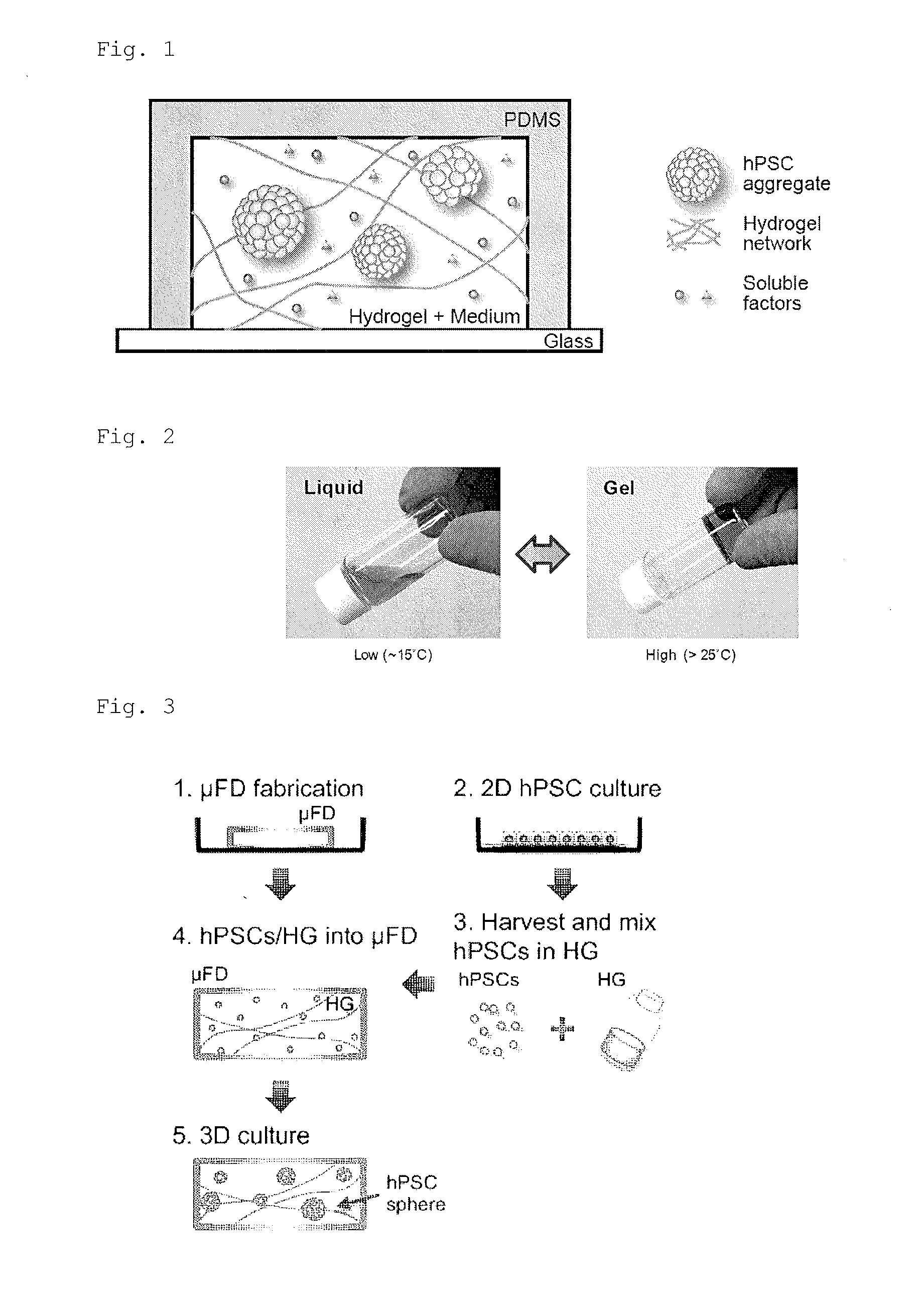
A 3D Culture Method for Human Pluripotent Stem Cells Using Mebiol Gel (Phase Transition Gel)

(1) Materials

[0093]Mebiol gel, Mebiol Inc., PMW20-1001 (10 mL for dilution)

mTeSR1

Veritas Corporation, ST-05850


PUM


Abstract

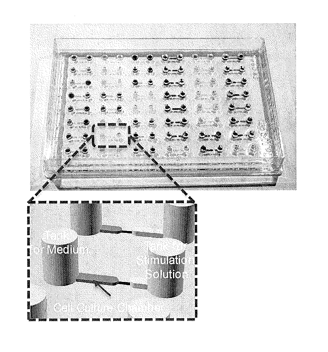
The present invention provides a microfluidic device comprising at least one cell culture chamber, the or each chamber being connected to at least two openings, the device being configured to supply at least one physiologically active substance from at least one of the openings to the or each cell culture chamber in such a manner as to form a concentration gradient or concentration gradients in the or each chamber when cells and a hydrogel are introduced into the or each chamber to culture the cells in a 3D-gel medium.

Description

TECHNICAL FIELD[0001]The present invention relates to a microfluidic device and a 3D cell microculture method.BACKGROUND ART[0002]The function of a cell in vivo is regulated in the extracellular microenvironment. The extracellular microenvironment consists mainly of (i) soluble factors such as growth factors, vitamins, and gas molecules, (ii) insoluble factors such as the stiffness of extracellular matrix proteins, and (iii) cell-cell interaction. These factors regulate the function of a cell while being intricately and strictly regulated. More specifically, in order to freely regulate the function of a target cell, such as a human ES cell and a human iPS cell, it is indispensable to freely regulate this extracellular microenvironment.[0003]However, the regulation occurs in an extremely small environment on a micrometer scale, and the traditional experimental cell culture technique using a 2D environment in a culture dish or a plate cannot reproduce the small environment. Thus, ther...

Claims


Application Information

Patent Timeline
IPC IPC(8): C12M1/12C12N5/00C12M3/06
CPCC12M25/14C12N2501/999C12N5/0062C12M23/16C12M35/08B33Y80/00C12N1/04C12N5/0696C12N2500/50C12N2513/00C12N2521/00C12N2523/00C12N2533/30C12N2539/10
Inventor KAMEI, KENICHIROCHEN, YONG
Owner KYOTO UNIV
Learn More