Mechanical clock movement with magnetic escapement

a mechanical clock and escapement technology, applied in the field of mechanical clock movement, can solve the problems of reducing pressure affecting etc., and achieves the effects of reducing mechanical friction, reducing power, and increasing the working precision of the watch

Active Publication Date: 2016-12-22
ETA SA MFG HORLOGERE SUISSE
View PDF13 Cites 7 Cited by
  • Summary
  • Abstract
  • Description
  • Claims
  • Application Information

AI Technical Summary

Benefits of technology

[0009]The aim of the present invention is to solve problems of the prior art in the case of watches equipped with a mechanical movement, in which it is provided to increase the quality factor of the oscillator by reducing vibrations due to air acting on the resonator. Moreover, the objective of the present invention is also to provide a mechanical watch that allows the chamber to also remain hermetically sealed during maintenance services, in particular when the oil traditionally provided on the bearings of various wheels must be renewed or a certain quantity of such an oil must simply be added to ensure correct lubrication of the wheels of the mechanical movement.
[0013]According to a preferred embodiment the mechanical movement does not have any wheel that pivots with a mechanical friction in the bearings in the hermetically sealed chamber. Thus, there is no need to supply oil to reduce the mechanical friction and to have a sliding friction with a film of oil. Therefore, firstly, no renewal of oil needs to be provided in the hermetically sealed chamber. Then, there is no risk of generating dust as a result of the pivoting movement of a wheel in the hole of a mechanical bearing. Moreover, this particular feature allows the working precision of the watch to be increased since the differences in working between various possible positions of the watch are minimised. Finally, such an embodiment also allows a reduction in the power necessary for maintaining the resonator and therefore for increasing the power reserve of the watch.

Problems solved by technology

In contrast, in the case of mechanical movements various significant problems have not enabled mechanical watches to be fabricated commercially with their movements each housed in a hermetic case, in which a reduced pressure prevails.
Firstly, mechanical watches generally have mechanical elements that pass through the case for the adjustment and / or operation of various functions, and this complicates the design of the case to enable this to ensure that a relatively stable reduced pressure is maintained over a long period.
Moreover, since the adjustment of the frequency of the resonator depends on the ambient pressure, this adjustment poses a manufacturing problem.
The solution comprising acting on an index using bimetallic blades by supplying an electric current or a light beam via the base of the case once the movement is encased and the low pressure has been established in particular poses a problem with respect to the precision of such an adjustment and a problem in the production process, since the individual adjustment of each watch must be done once the movement has been encased.
Hence, apart from a process that enables a particular device in the watch to be omitted in order to conduct the adjustment of the working thereof under reduced pressure, all the other problems remain.

Method used


Image

  • Mechanical clock movement with magnetic escapement
  • Mechanical clock movement with magnetic escapement
  • Mechanical clock movement with magnetic escapement

Examples


first embodiment

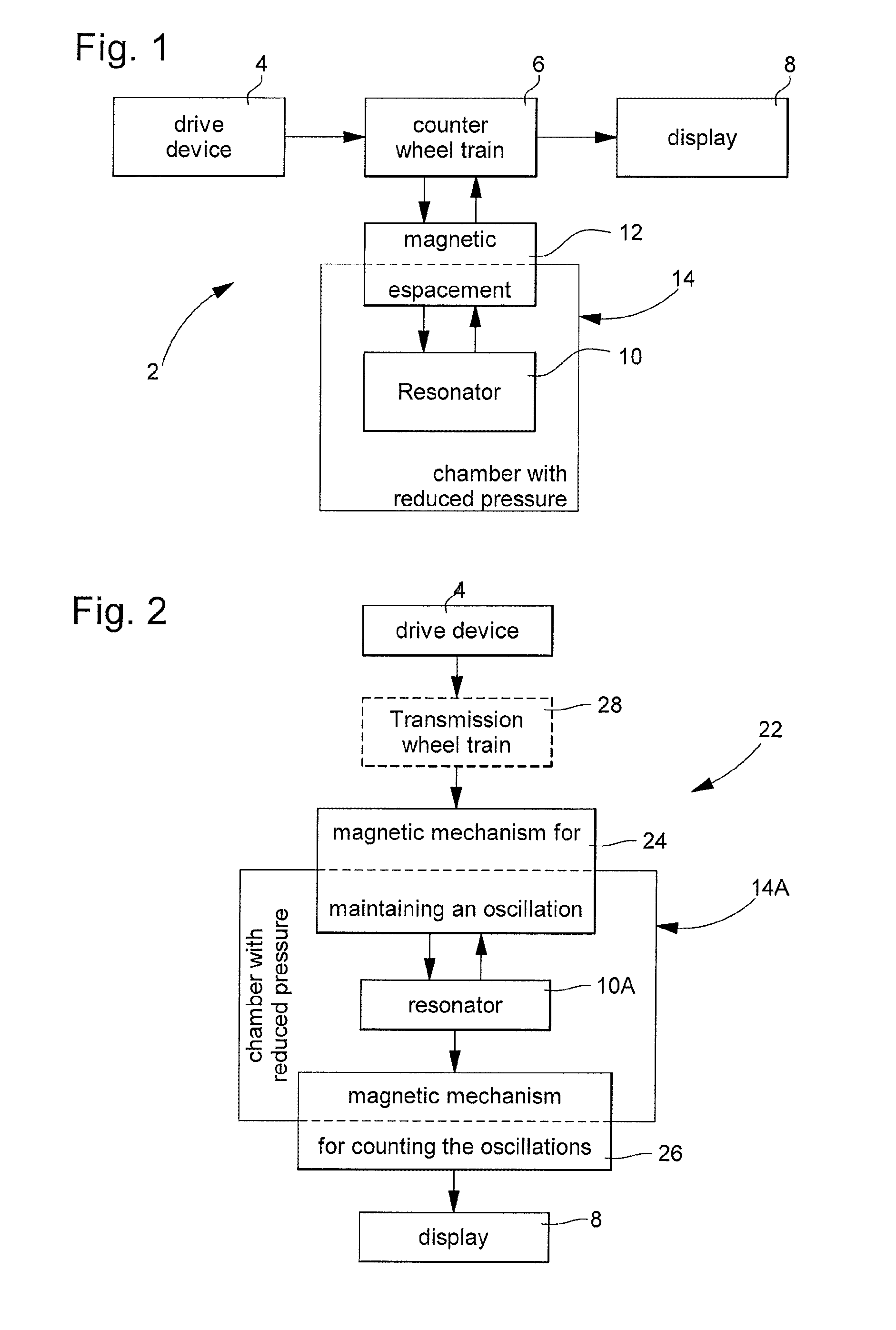
[0027]It will be observed that the magnetic mechanism for maintaining oscillation can be similar in design to a magnetic escapement such as that of the first embodiment, and can therefore correspond, for example, to one of the particular embodiments that will be described below. The same observation applies to the counting and drive magnetic mechanism. In particular, at least one of these two magnetic mechanisms comprises an escape wheel coupled directly or indirectly to the resonator 10A via a magnetic coupling system. This magnetic coupling system is formed from at least one first magnetic element and a second magnetic element that exhibit at least periodically a magnetic interaction between them. According to the invention there is provided a hermetically sealed chamber 14A, which comprises a wall running between the first and second magnetic elements, so that the first magnetic element is inside the chamber, whereas the second magnetic element and the escape wheel are outside th...

third embodiment

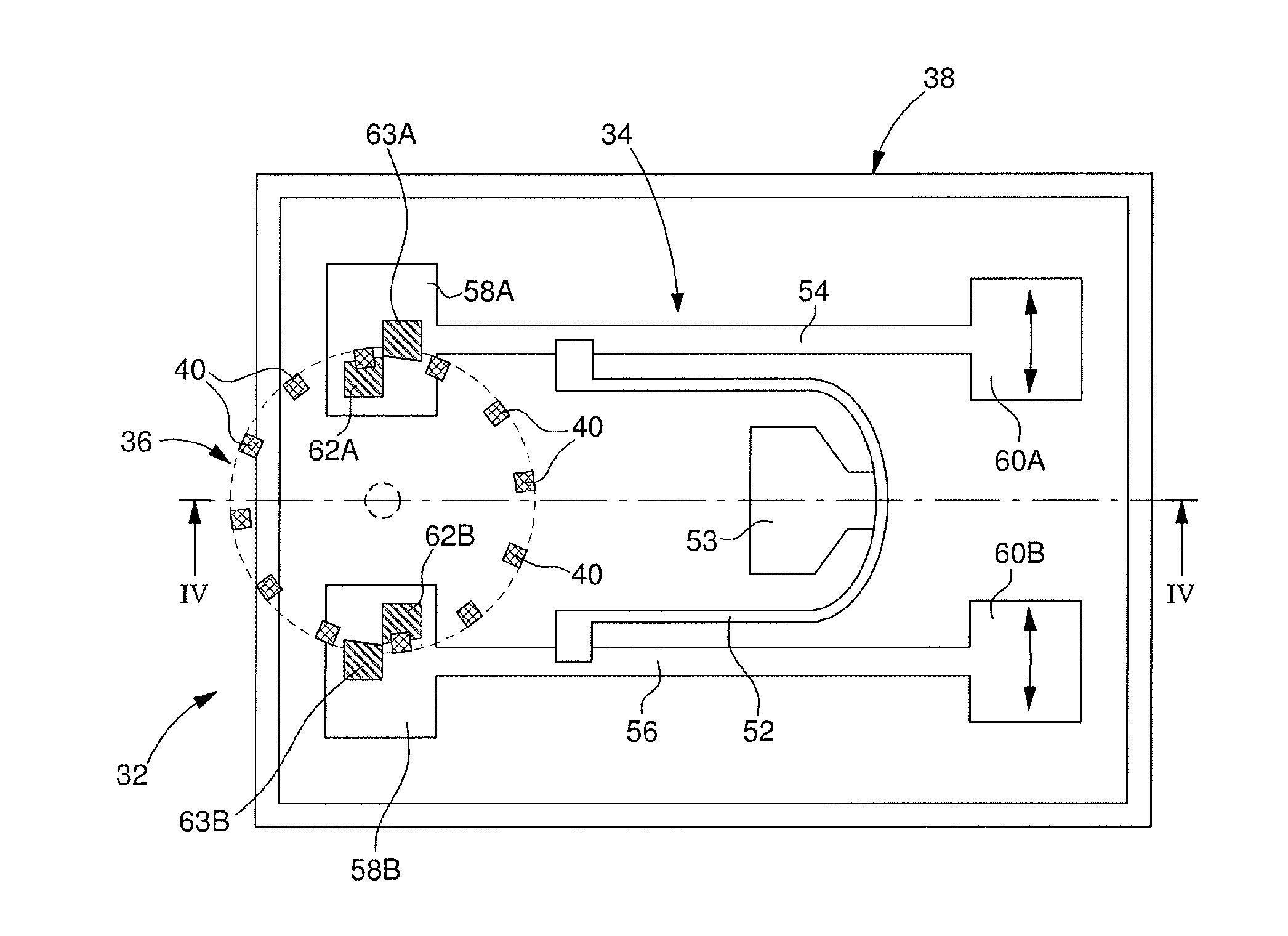
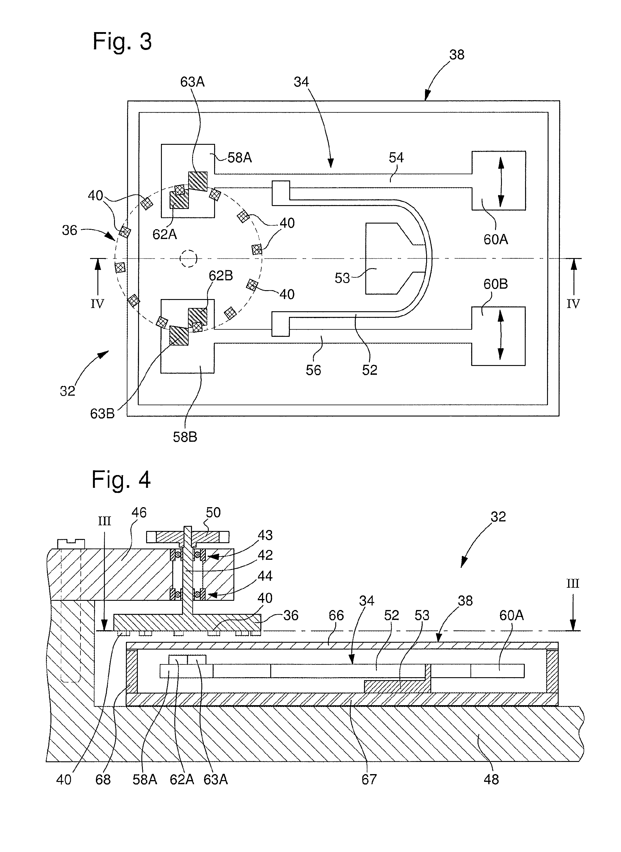
[0029]a clock movement according to the invention is described below with reference to FIGS. 3 and 4. The mechanical clock movement 32 is shown only partially in the figures in order to reveal the features specific to the invention that relate to the regulating device of this movement. This third embodiment as well as the other embodiments that will be described below are particular configurations of the first general embodiment described above. Apart from a wheel or a pinion used for mechanical coupling of the escape wheel to the drive device and to the counter wheel train, this drive device and this counter wheel train as well as the display device are not shown in the figures nor described in detail, since they are known to the person skilled in the art. In fact, the present invention is noteworthy because of these parts of the mechanical movement and the devices that are generally associated with them, in particular the winding device, the device for correcting time information ...

fourth embodiment

[0042]The variant of the fourth embodiment shown in FIGS. 5 and 6 is noteworthy in that the clock movement 72 largely incorporates components and elements of traditional clockmaking while using a magnetic coupling system without contact between the anchor and the escaped wheel to allow a wall 112 of a hermetically sealed chamber 80 to be located between first and second parts of this magnetic coupling system of the escapement.

[0043]A fifth embodiment of a clock movement according to the invention is described below with reference to FIGS. 7, 8 and 9A to 9D. The mechanical clock movement 152 comprises a resonator 154 and a magnetic escapement 156 shown in the figures. As in the fourth embodiment, this magnetic escapement comprises an escape wheel 158, which is coupled to the resonator by an intermediate member 160 formed by an anchor defining a bistable retaining catch. In contrast, this fifth embodiment differs from the previous embodiment in that the magnetic coupling system of the...


PUM


Abstract

A mechanical clock movement includes a resonator, an escapement linked to the resonator, and a display of at least one item of time information. The display is driven by a mechanical drive device via a counter wheel train, the work rate of which is set by the escapement. At least the resonator is housed in a chamber, in which a reduced pressure in relation to atmospheric pressure prevails. The escapement is a magnetic escapement including an escape wheel coupled directly or indirectly to the resonator via a non-contact magnetic coupling system, wherein the magnetic coupling system is formed so that a non-magnetic wall of the chamber runs through the magnetic escapement so that a first part of the escapement is located inside the chamber whereas a second part of the escapement is located outside the chamber.

Description

TECHNICAL FIELD[0001]The present invention relates to a mechanical clock movement equipped with a device for regulating its working formed by a resonator linked with an escapement. Escapement is understood in the clockmaking field to mean a system formed by a mechanism for maintaining oscillation of the resonator and a mechanism for counting this oscillation to set the work rate of a display of at least one item of time information. The resonator and the mechanism for maintaining its oscillation together define an oscillator. It will be noted that the mechanism for maintaining oscillation and the counting mechanism are formed by the very same mechanism for the distribution of energy supplied by a drive device, which perform both functions.[0002]More specifically, the present invention is concerned with increasing the quality factor of the regulator device in order to improve the working precision of the mechanical clock movement, in particular to improve the isochronism of the oscil...

Claims


Application Information

Patent Timeline
Patent Type & Authority Applications(United States)
IPC IPC(8): G04B37/08G04C3/08G04C5/00
CPCG04B37/088G04C3/08G04C5/005G04B3/046G04B17/045G04B17/06G04B17/26G04B37/02G04B15/14G04B17/32G04C3/105G04B17/063G04B17/24G01C5/00
Inventor WINKLER, PASCALHELFER, JEAN-LUCCONUS, THIERRYDI DOMENICO, GIANNIBORN, JEAN-JACQUES
Owner ETA SA MFG HORLOGERE SUISSE
Why Eureka
Try Eureka