Radiographic image detector

Active Publication Date: 2016-12-22
KONICA MINOLTA INC
View PDF0 Cites 4 Cited by
  • Summary
  • Abstract
  • Description
  • Claims
  • Application Information

AI Technical Summary

Benefits of technology

The invention aims to prevent a rise in temperature in a scintillator caused by heat generated from an electric circuit or other components in a FPD. The invention aims to suppress temperature quenching and variations in in-plane brightness of an image.

Problems solved by technology

The CsI scintillator has a problem in that the amount of emitted light decreases with increasing temperature.
FPDs, which generally have a heat source such as an electric circuit in the case, also have a problem in that they are potentially more easily heated than CRs without such a heat source.
There is a problem in that such temperature quenching causes a reduction in the amount of the light emitted by the scintillator.
In addition, there is another problem in that local variations in the thermal energy applied to the scintillator occur depending on the location and other conditions of the heat source in the case, so that variations occur in the amount of emitted light in the plane of the panel (brightness unevenness).
However, the thermal energy generated from the heat source can randomly change depending on the use conditions, and correction is impossible in some case, which raises a problem.
However, these measures are not based on an idea for suppressing the phenomenon of heat transfer from a heat source such as a circuit board to a scintillator.
Therefore, even when these measures are used, an unacceptable reduction in the amount of emitted light from a scintillator or unacceptable variations in brightness can occur depending on the situation where a heat source generates heat.

Method used


Image

  • Radiographic image detector
  • Radiographic image detector
  • Radiographic image detector

Examples


examples

[0141]Hereinafter, the present invention will be more specifically described with reference to examples, which, however, are not intended to limit the present invention.

production examples

[0142]A 125-μm-thick polyimide film (UPILEX-125S manufactured by Ube Industries, Ltd.) was used as a support. A 3-μm-thick coating of VYLON RESIN (manufactured by TOYOBO CO., LTD.), crystalline polyester, was formed as an adhesion layer on the surface of the support, where a phosphor was to be deposited. The coated support was then cut to form a support for vapor deposition. A CsI phosphor was vapor-deposited on the resulting support in vacuo under the conditions described in JP 2015-021886 A. The vapor deposition was completed when the thickness of the CsI film reached 200 μm.


PUM


Abstract

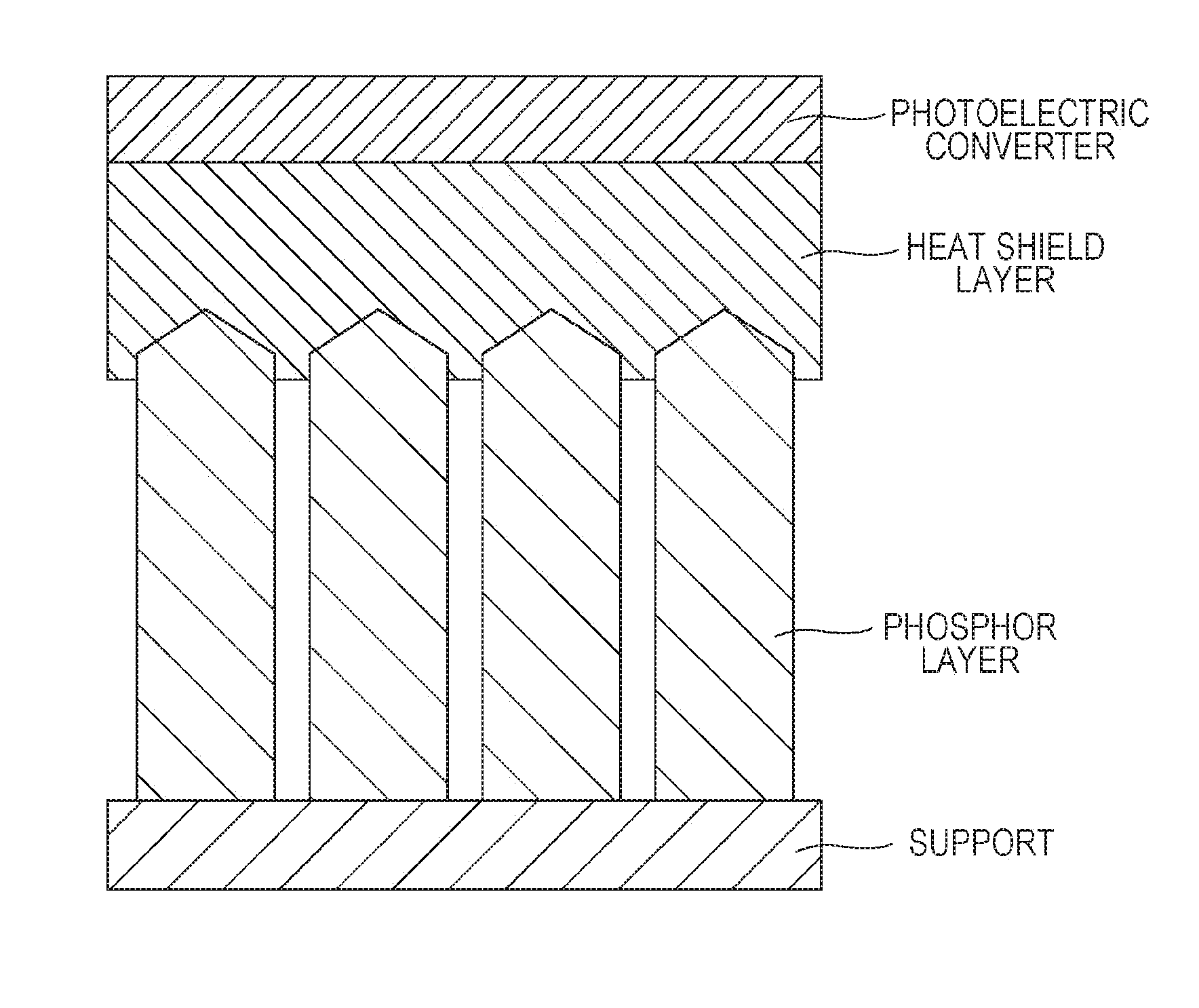
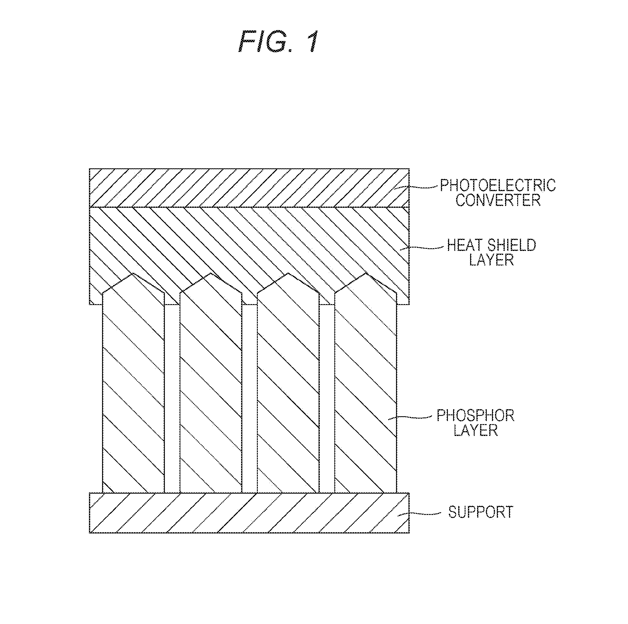
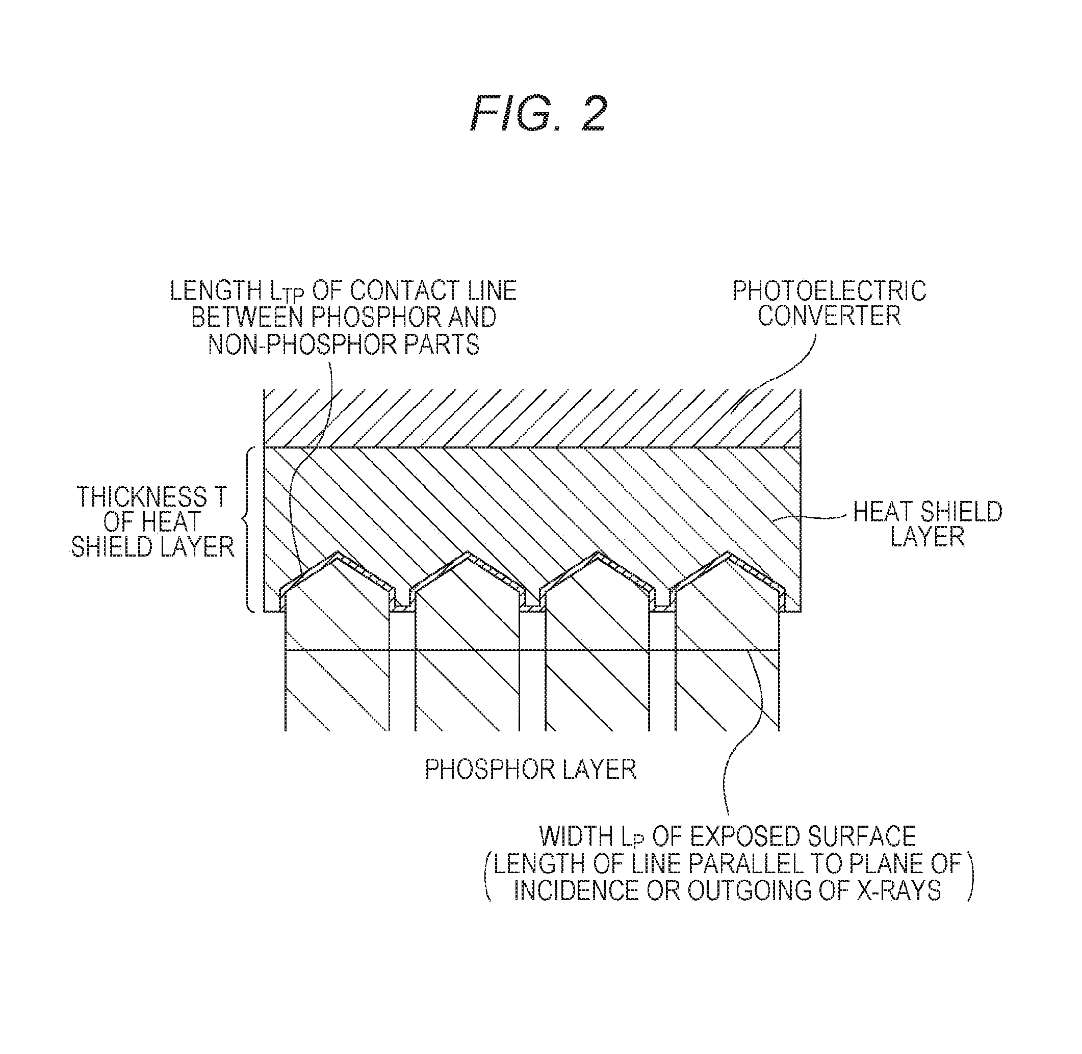
A radiographic image detector includes a phosphor layer, a heat shield layer, and a photoelectric converter in this order, wherein the heat shield layer has a thickness T (μm) and a thermal conductivity C (W / m·K) satisfying that C / T is from 0.004 to 5.

Description

[0001]The entire disclosure of Japanese Patent Application No. 2015-120956 filed on Jun. 16, 2015 including description, claims, drawings, and abstract are incorporated herein by reference in its entirety.BACKGROUND OF THE INVENTION[0002]Field of the Invention[0003]The present invention relates to a radiographic image detector capable of suppressing temperature quenching of the scintillator, which is associated with temperature rise, and also capable of suppressing unevenness in the in-plane brightness of the image.[0004]Description of the Related Art[0005]In recent years, digital radiographic image detectors such as computed radiography (CR) systems and flat panel detectors (FPDs), which allow directly obtaining digital radiographic images and directly displaying images on image displays such as cathode-ray tubes and liquid crystal panels, are widely used for diagnostic imaging in hospitals, clinics, and other places. Recently, a flat panel using a cesium iodide (CsI)-containing sc...

Claims


Application Information

Patent Timeline
IPC IPC(8): H01L31/024H01L27/146
CPCH01L31/024H01L27/14658H01L27/14676H01L27/14663G01T1/20188
Inventor ISODA, KEIKONDO, MASASHIARIMOTO, TADASHI
Owner KONICA MINOLTA INC
Why Eureka
Try Eureka