Power generation system exhaust cooling

Active Publication Date: 2016-12-29
GENERAL ELECTRIC CO
View PDF5 Cites 24 Cited by
  • Summary
  • Abstract
  • Description
  • Claims
  • Application Information

AI Technical Summary

Benefits of technology

[0006]A first aspect of the disclosure provides a system for reducing a temperature of an exhaust gas stream of a gas turbine system, including: a compressor component of a gas turbine system; an airflow generation system for attachment to a rotatable shaft of the gas turbine system, the airflow generation system and the compressor component drawing in an excess flow of air through an air intake section; a mixing area for receiving an exhaust gas str

Problems solved by technology

Because of the possibility of catalyst damage due to a failure of an external blower system, a redundant external blower system is typically utilized.
These external blower systems include many components, such as blowers, motors, filters, air intake structures, and large ducts, which are expensive, bulky, and add to

Method used


Image

  • Power generation system exhaust cooling
  • Power generation system exhaust cooling
  • Power generation system exhaust cooling

Examples


Example

[0021]It is noted that the drawing of the disclosure is not to scale. The drawing is intended to depict only typical aspects of the disclosure, and therefore should not be considered as limiting the scope of the disclosure. In the drawing, like numbering represents like elements between the drawings.

DETAILED DESCRIPTION OF THE INVENTION

[0022]As indicated above, the disclosure relates generally to power generation systems, and more particularly, to systems and methods for cooling the exhaust gas of power generation systems.

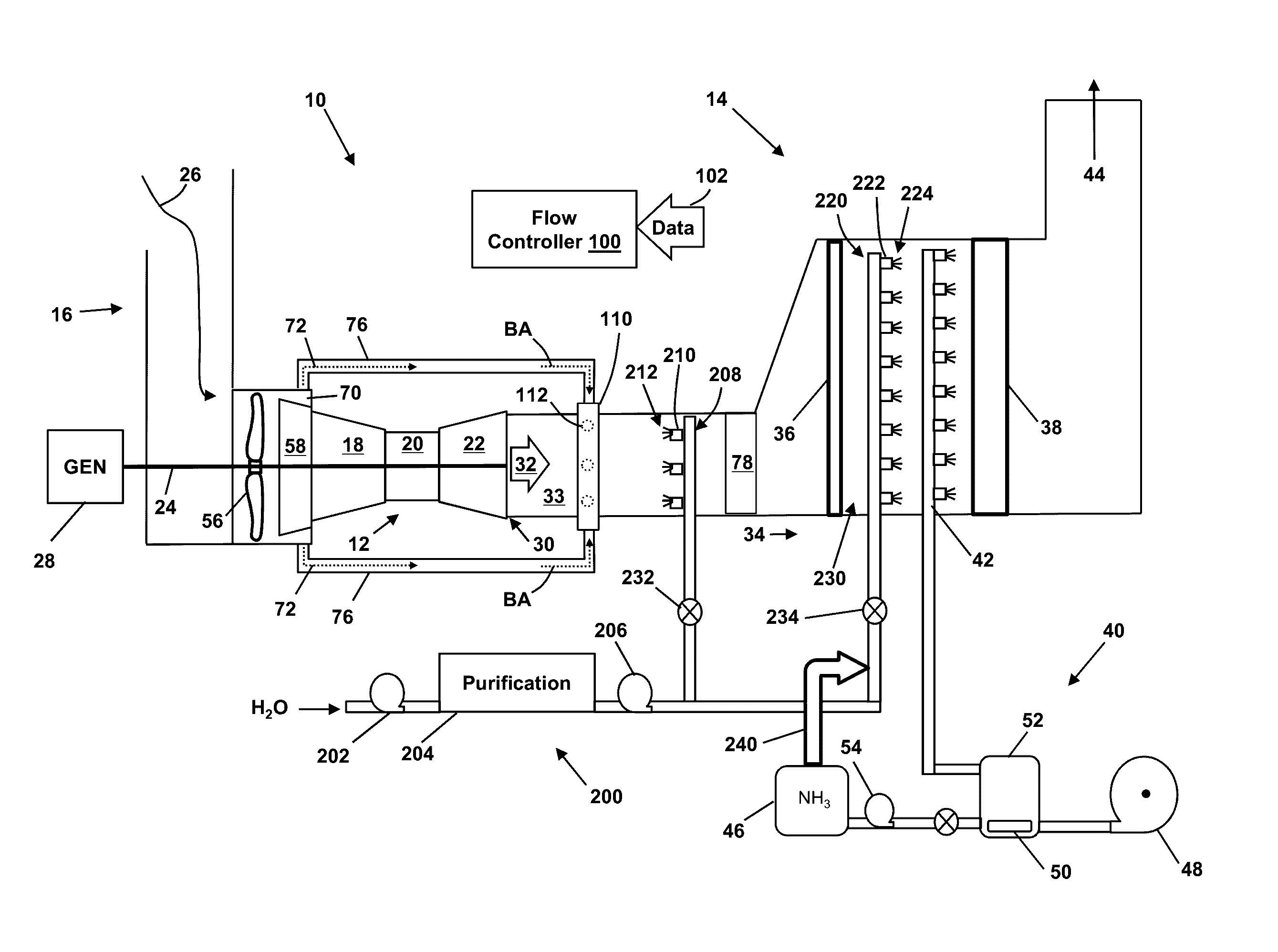
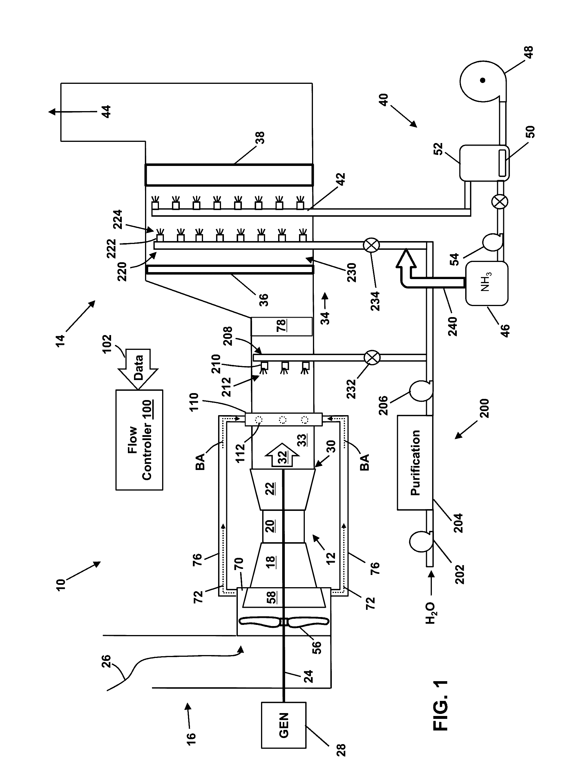
[0023]FIGS. 1 and 3 depict block diagrams of turbomachine systems (e.g., simple cycle gas turbine power generation systems 10) that include a gas turbine system 12 and an exhaust processing system 14. The gas turbine system 12 may combust liquid or gas fuel, such as natural gas and / or a hydrogen-rich synthetic gas, to generate hot combustion gases to drive the gas turbine system 12.

[0024]The gas turbine system 12 includes an air intake section 16, a compressor comp...


PUM


Abstract

A system for reducing a temperature of an exhaust gas stream of a gas turbine system according to an embodiment includes: a compressor component of a gas turbine system; an airflow generation system for attachment to a rotatable shaft of the gas turbine system, the airflow generation system and the compressor component drawing in an excess flow of air through an air intake section; a mixing area for receiving an exhaust gas stream produced by the gas turbine system; an air extraction system for: extracting at least a portion of the excess flow of air generated by the airflow generation system and the compressor component to provide bypass air; and diverting the bypass air into the mixing area to reduce a temperature of the exhaust gas stream; and a fluid injection system for injecting an atomized fluid into the mixing area to reduce a temperature of the exhaust gas stream.

Description

CROSS-REFERENCE TO RELATED APPLICATIONS[0001]This application is related to co-pending U.S. application Ser. Nos.: ______, GE docket numbers 280650-1, 280685-1, 280687-1, 280688-1, 280692-1, 280707-1, 280730-1, 280731-1, 280815-1, 281003-1, 281004-1, 281005-1and 281007-1 all filed on ______.BACKGROUND OF THE INVENTION[0002]The disclosure relates generally to power generation systems, and more particularly, to systems and methods for cooling the exhaust gas of power generation systems.[0003]Exhaust gas from power generation systems, for example a simple cycle gas turbine power generation system, often must meet stringent regulatory requirements for the composition of the exhaust gas released into the atmosphere. One of the components typically found in the exhaust gas of a gas turbine power generation system and subject to regulation is nitrogen oxide (i.e., NOx), which includes, for example, nitric oxide and nitrogen dioxide. To remove NOx from the exhaust gas stream, technology suc...

Claims


Application Information

Patent Timeline
IPC IPC(8): F01N3/05F02C3/04F02C3/30F01N3/20
CPCF01N3/05F01N3/2066F05D2220/32F02C3/30F02C3/04F01N13/009F01N3/04F01N3/2073F02C6/00F02C7/16F01N2570/14F01N2610/02F01N2610/14F05D2260/606F05D2260/212F01D25/305F02C7/141F02C9/18F05D2270/082F05D2250/80F01N2590/10F01N2610/08Y02T10/12
Inventor KULKARNI, PARAG PRAKASHDAVIS, JR., LEWIS BERKLEYREED, ROBERT JOSEPH
Owner GENERAL ELECTRIC CO
Why Eureka
Try Eureka