Dynamic power management optimization

a technology of dynamic power management and optimization, applied in the direction of power supply for data processing, climate sustainability, instruments, etc., can solve the problems of leakage current, power consumption, and higher amount of power consumed, so as to increase the wake-up interval, and increase the duration of the wake-up timer

Inactive Publication Date: 2016-12-29
ADVANCED MICRO DEVICES INC
View PDF5 Cites 34 Cited by
  • Summary
  • Abstract
  • Description
  • Claims
  • Application Information

AI Technical Summary

Benefits of technology

[0009]In one embodiment, a power management unit on an integrated circuit may determine whether or not measured activity of any of a plurality of compute units exceeds one or more thresholds. For example, in one embodiment, a processor (e.g., a CPU) of the integrated circuit may be idle, but software may periodically wake the CPU up to check for any background downloads or other activity that may need attention. In various embodiments, the background downloads may be for social media applications (e.g., Facebook, Twitter, LinkedIn), new emails, and so on. By periodically waking up and performing the background downloads, this ensures that the user will see the updated status the next time the user starts using the host device (e.g., smartphone, tablet). When the CPU wakes up, if the CPU determines that there is not much work to be done, then the wake-up interval can be increased. As long as the CPU keeps waking up and determines there is less than a threshold amount of work to do, then the wake-up interval can keep increasing. In some embodiments, the power management unit may track measured activity, wherein the measured activity includes one or more of memory accesses, input/output (I/O) accesses, instructions executed, and/or one or mor

Problems solved by technology

In particular, the small feature sizes of transistors in ICs can result in leakage currents and thus power consumption even in functional units that are otherwise not performing any work.
Generally speaking, hi

Method used


Image

  • Dynamic power management optimization
  • Dynamic power management optimization
  • Dynamic power management optimization

Examples


Embodiment Construction

[0021]In the following description, numerous specific details are set forth to provide a thorough understanding of the methods and mechanisms presented herein. However, one having ordinary skill in the art should recognize that the various embodiments may be practiced without these specific details. In some instances, well-known structures, components, signals, computer program instructions, and techniques have not been shown in detail to avoid obscuring the approaches described herein. It will be appreciated that for simplicity and clarity of illustration, elements shown in the figures have not necessarily been drawn to scale. For example, the dimensions of some of the elements may be exaggerated relative to other elements.

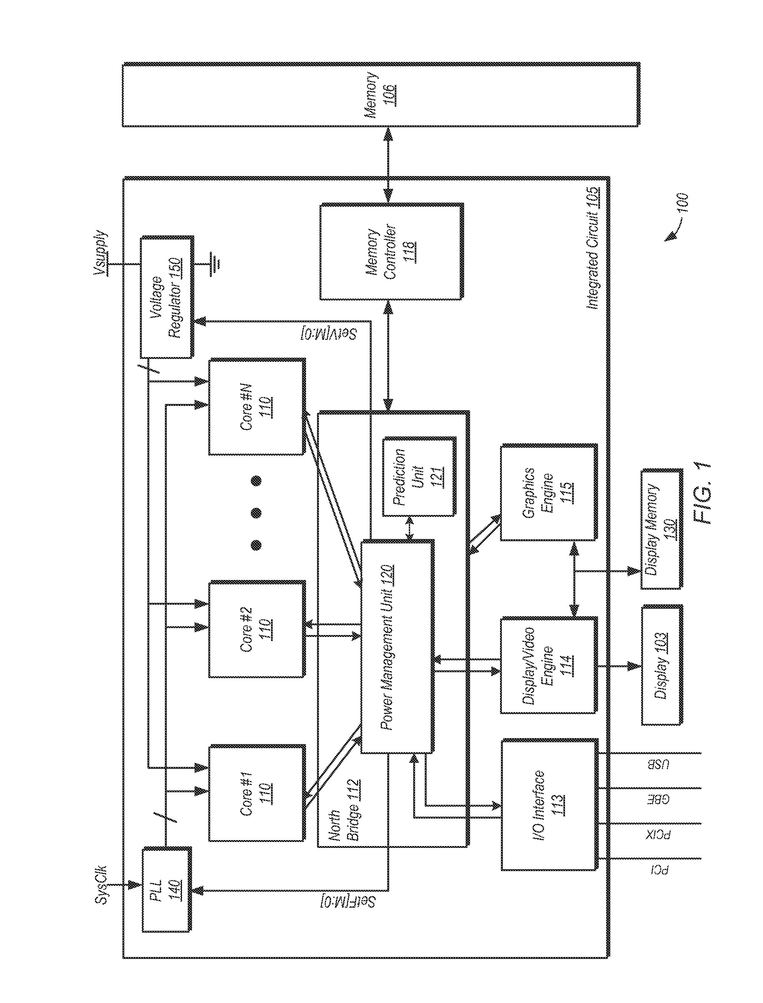
[0022]Referring now to FIG. 1, a block diagram of one embodiment of an integrated circuit (IC) 105 coupled to a memory 106 is shown. IC 105 and memory 106, along with display 103 and display memory 130, form at least a portion of computer system 100 in this examp...


PUM


Abstract

Systems, apparatuses, and methods for managing power usage of integrated circuits. One or more processor cores may be powered down when the system is idle. Even if there is no user activity, the processor core(s) may be woken up periodically for background downloads to retrieve the latest status for social media and other applications. Additionally, a power management unit may track the average number of active cores and the average core utilization. If the average number of active cores is less than a first threshold and the average core utilization is less than a second threshold, the power management unit may generate a request to offline one or more cores. Still further, when the processor's skin temperature is above a threshold and all of the cores are operating at the lowest acceptable operating point, one or more cores may be powered down.

Description

BACKGROUND[0001]Technical Field[0002]Embodiments described herein relate to integrated circuits and more particularly, to managing power consumption of integrated circuits.[0003]Description of the Related Art[0004]Managing power consumption in integrated circuits (ICs) such as computer system processors and various types of system-on-a-chip (SoC) ICs is increasingly important. This is true not only during times when an IC is actively performing work, but also during times when the IC is idle. In particular, the small feature sizes of transistors in ICs can result in leakage currents and thus power consumption even in functional units that are otherwise not performing any work.[0005]When a functional unit of an IC becomes idle, power management hardware or software may take various actions to reduce power consumption. Reducing clock frequencies or gating clocks may reduce dynamic power consumption. Reducing a supply voltage may provide additional reductions in power consumption. In s...

Claims


Application Information

Patent Timeline
IPC IPC(8): G06F1/32
CPCG06F1/3296G06F1/3287G06F1/3203G06F1/3237G06F1/324G06F1/3243G06F1/329Y02D10/00
Inventor BRANOVER, ALEXANDER J.JAIN, ASHISHGADA, SRIDHAR V.
Owner ADVANCED MICRO DEVICES INC
Why Eureka
Try Eureka