Mechanical assist device

a technology of mechanical assist and device, which is applied in the field of mechanical assist devices, can solve the problems of system invasive and cumbersome operation, device is not fully implanted in the chest cavity, and severe complications, and achieves the effect of improving the overall ejection of blood from the chamber

Inactive Publication Date: 2017-01-05
PRESIDENT & FELLOWS OF HARVARD COLLEGE +1
View PDF10 Cites 27 Cited by
  • Summary
  • Abstract
  • Description
  • Claims
  • Application Information

AI Technical Summary

Benefits of technology

[0007]The inventors have appreciated that it would be advantageous to employ a device within certain regions of the body that mechanically assists contractile motion at the region(s) of interest, in an active manner. For example, an actuator may be anchored at opposing tissue wall locations of a chamber (e.g., right ventricle, left ventricle, right atrium, left atrium) of a heart. The actuator, along with the anchors to which the actuator is coupled, may be configured to assist in suitable contraction of the chamber, at appropriate times. For instance, the device may be suitably synchronized with the pacing of the heart, assisting in contraction of a chamber in which the device is implanted, so as to improve overall ejection of blood from the chamber.

Problems solved by technology

Heart failure is one of the leading causes of death worldwide.
While a number of methods of treatment have been developed for various types of heart failure, the options for treating certain types of heart failure, such as right ventricular heart failure, are limited and can lead to severe complications.
Not only does this device require open-heart surgery to implant, the device is not fully implantable within the chest cavity.
Such a system is both invasive and cumbersome to operate.
However, by virtue of the jacket being in continuous contact with the heart and applying repeated compressive force to the heart, such a jacket may undesirably affect the external vasculature of the heart.
For example, the jacket may detrimentally impinge on or damage blood vessels that nourish the heart.

Method used


Image

  • Mechanical assist device
  • Mechanical assist device
  • Mechanical assist device

Examples


Embodiment Construction

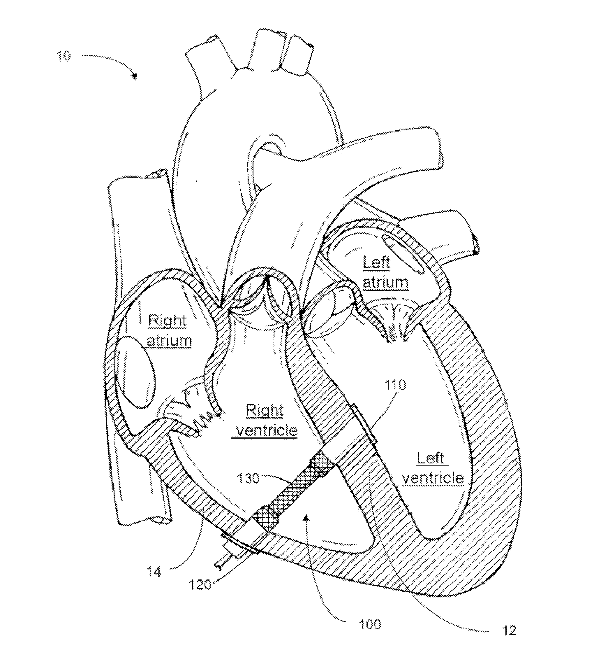
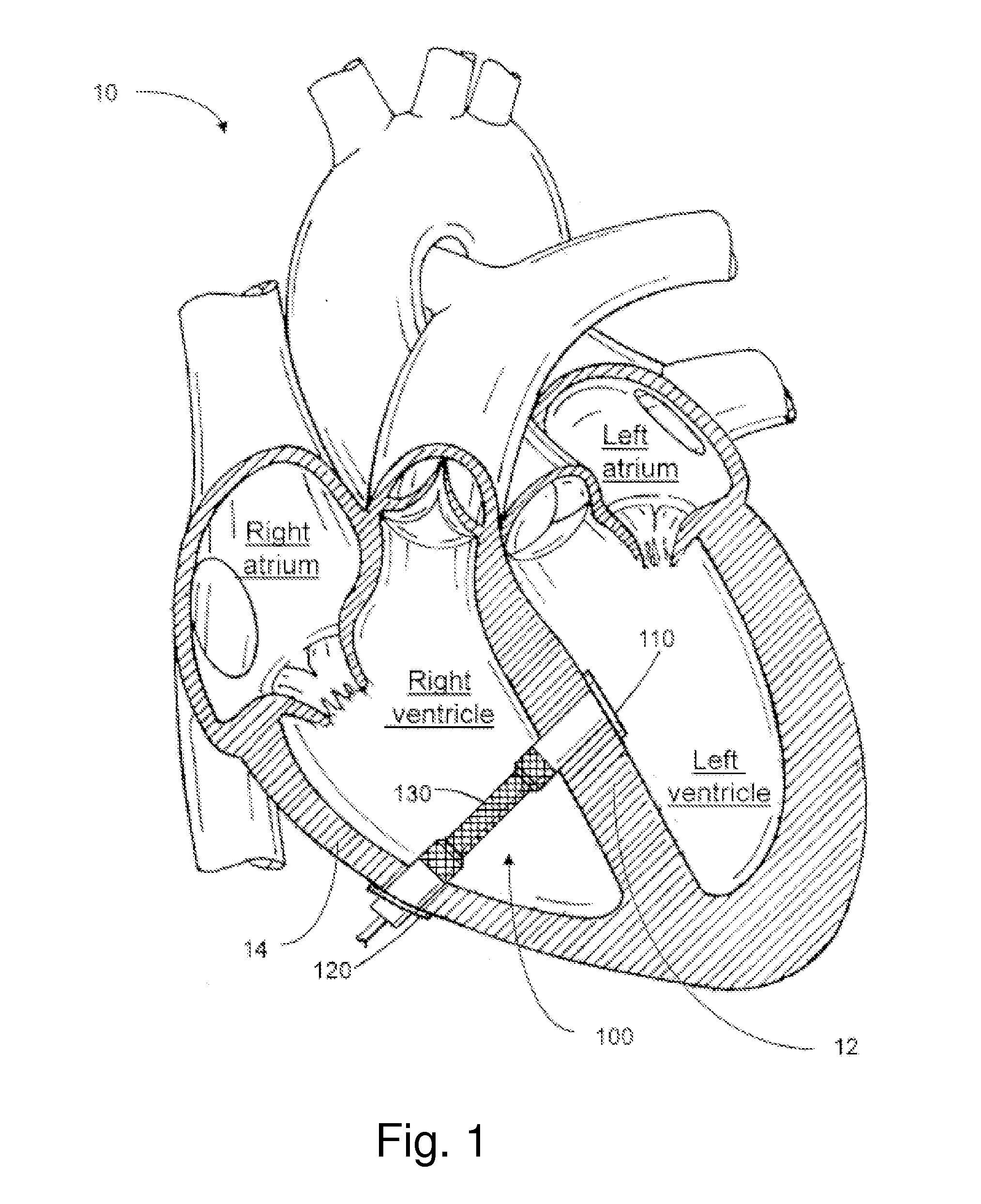
[0035]The present disclosure relates to an implantable device that may be configured to provide active mechanical assistance to the region (e.g., within an organ) at which the device is implanted. For example, the device may be implanted within a right ventricle of the heart, or left ventricle, and may provide a suitable degree of contractile assistance to the respective ventricle. Such contractile assistance may be coordinated with the natural cyclic pacing of the heart, so as to improve the overall ejection fraction of blood from the chamber in which the device is implanted.

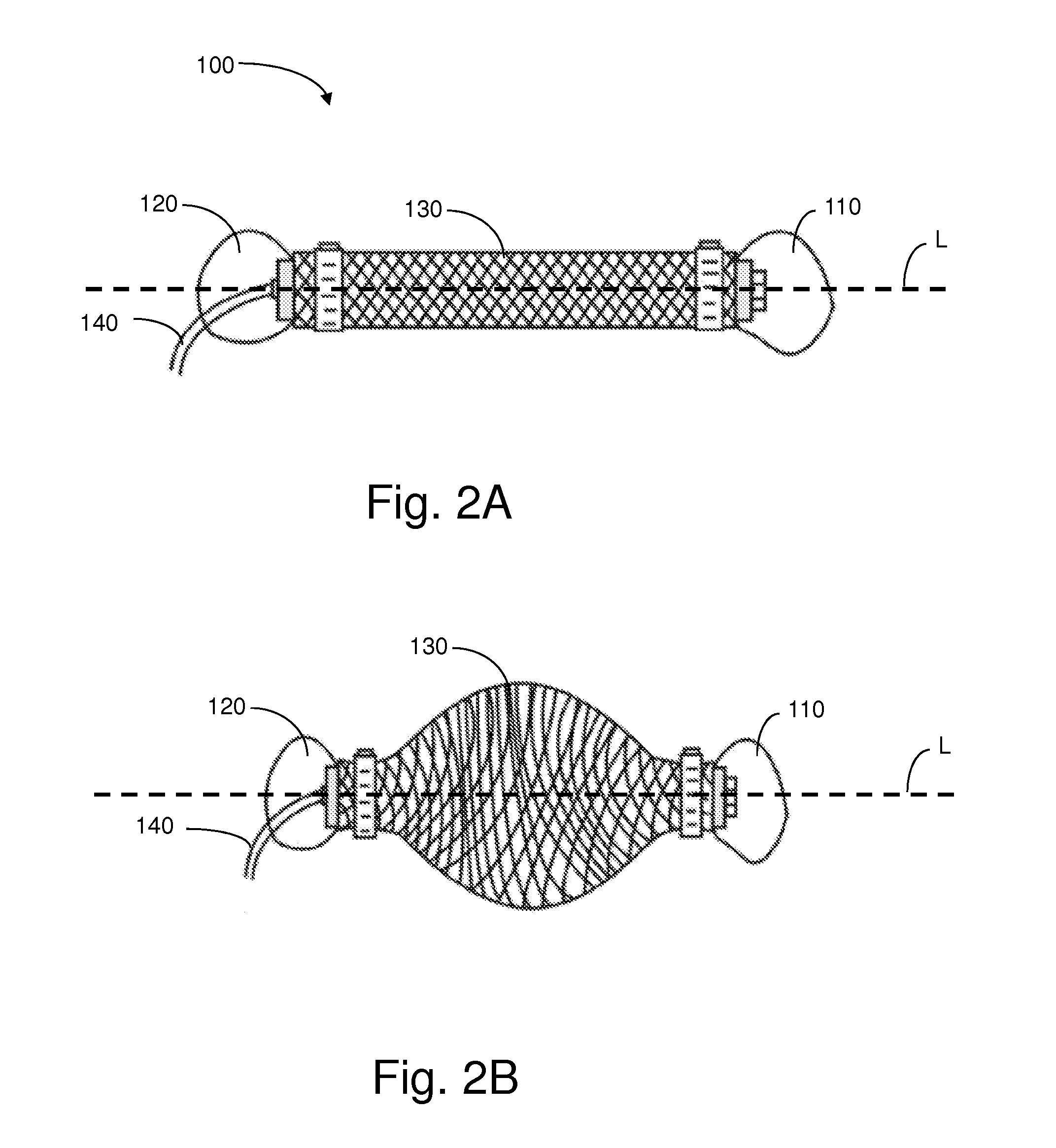
[0036]The device may have a number of anchors for engaging with the tissue wall(s) of an organ. The device may also include an actuator coupled to each of the anchors. The actuator may cause the respective anchors to which it is coupled, and hence the tissue wall to which the anchors are engaged, to move back and forth relative to one another in a repeated motion.

[0037]In some embodiments, the actuator is locat...


PUM


Abstract

Methods and apparatuses relate to an implantable device for providing contractile assistance to an organ. The device may include an actuator and anchors located on either side of the actuator. The anchors engage with oppositely positioned tissue walls of an organ chamber, and provide contractile assistance to the organ, repeatedly, at appropriate times. For example, the device may be implanted within the right ventricle, anchored to the right ventricular free wall and the ventricular septum. The device may function to bring the opposing walls of the ventricle toward one another, synchronized with the pacing of the heart, resulting in an improved ejection fraction of blood from the chamber. In some embodiments, the actuator includes a bladder that is configured to contract upon receiving an inflow of pressurized fluid therein. When the fluid exits therefrom, the bladder relaxes back to an initial, extended state.

Description

BACKGROUND[0001]1. Field[0002]Aspects herein relate to mechanical assist devices for implantation in tissue and methods of use.[0003]2. Discussion of Related Art[0004]Heart failure is one of the leading causes of death worldwide. While a number of methods of treatment have been developed for various types of heart failure, the options for treating certain types of heart failure, such as right ventricular heart failure, are limited and can lead to severe complications.[0005]For example, one existing method of treatment employs a continuous flow device having a tube through which blood flows and is actively pumped between the different chamber(s) of the heart. Not only does this device require open-heart surgery to implant, the device is not fully implantable within the chest cavity. That is, during use, the blood circulates both inside and outside of the body. Such a system is both invasive and cumbersome to operate. Further, use of such devices also require that anticoagulants (e.g....

Claims


Application Information

Patent Timeline
Patent Type & Authority Applications(United States)
IPC IPC(8): A61M1/12A61B5/042A61M1/10
CPCA61M1/122A61M1/1068A61M1/106A61M2230/005A61B5/042A61M2230/04A61M1/1086A61B17/0401A61B2017/00243A61B2017/0404A61B2017/0417A61M2205/0283A61M2205/32A61M2205/33A61M2205/3303A61M60/289A61M60/486A61M60/861A61M60/865A61M60/187A61M60/468A61M60/515A61M60/484A61M60/148
Inventor VASILYEV, NIKOLAY V.DEL NIDO, PEDRO J.LIEVANO BELTRAN, TONATIUH M.KRAUS, ERIK A.MEHANDRU, NIKHILPARK, EVELYN J.WALSH, CONOR J.WAMALA, ISAAC
Owner PRESIDENT & FELLOWS OF HARVARD COLLEGE
Why Eureka
Try Eureka