
Method for producing solar cells and solar cell assemblies

a solar cell and solar cell technology, applied in the field of photovoltaic power devices, can solve the problems of inefficient use of surface on which the solar cell is mounted, inefficient use of available space, and increase the overall cost of the photovoltaic may or panel, so as to achieve high wafer utilization, facilitate combination, and high packing factor

Inactive Publication Date: 2017-01-12
SOLAERO TECH CORP
View PDF7 Cites 7 Cited by
  • Summary
  • Abstract
  • Description
  • Claims
  • Application Information

AI Technical Summary

Benefits of technology

The patent describes a method for producing solar cells by dividing a non-rectangular solar cell wafer into multiple smaller solar cells. By doing so, the wafer can be utilized more efficiently, with high packing factors and reduced waste of material. The first solar cell can be shaped like a square or octagon to enhance the overall efficiency of the solar cell assembly. The use of a relatively small number of solar cells is preferred to minimize interconnections. The solar cell wafer can be a III-V compound semiconductor multijunction solar cell wafer, which is relatively high-cost material that can be efficiently utilized without excessive interconnections. In summary, the patent provides a method for producing high-quality solar cells with maximized efficiency and reduced waste of material.

Problems solved by technology

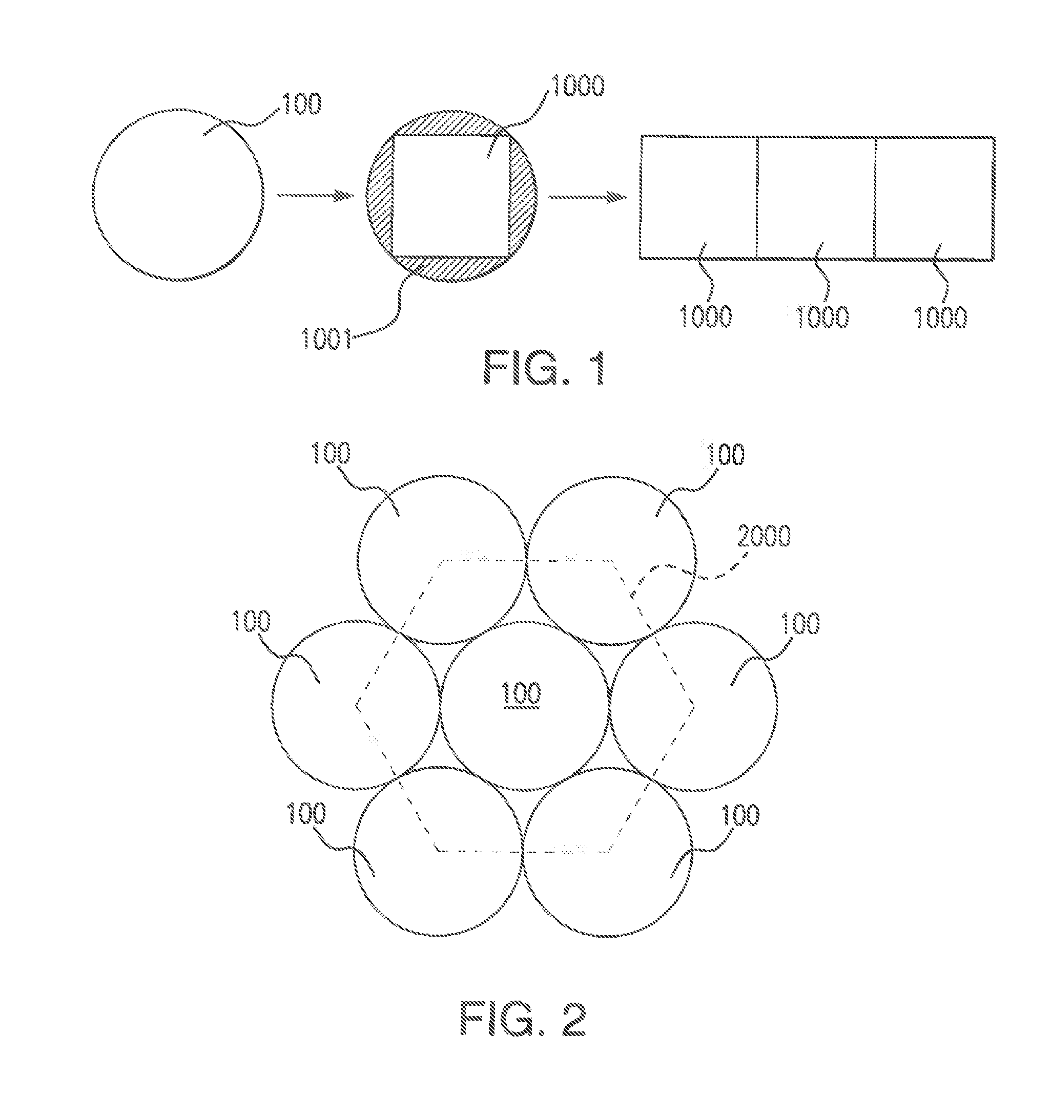
Arrays of substantially circular solar cells are known to involve the drawback of inefficient use of the surface on which the solar cells are mounted, due to space that is not covered by the circular solar cells due to the space that is left between adjacent solar cells due to their circular configuration (cf.
However, as explained above, for assembly into a solar array (henceforth, also referred to as a solar cell assembly), substantially circular solar cells, which can be produced from substantially circular wafers to minimize wasting wafer material and, therefore, minimize solar cell cost, are often not the best option, due to their low array packing factor, which increases the overall cost of the photovoltaic may or panel and implies an inefficient use of available space.
However, when a single circular wafer is divided into a single rectangular solar cell, the wafer utilization is low.
This results in waste of the solar cell wafer material.
High efficiency solar cell wafers are often costly to produce.
Thus, the waste that has conventionally been accepted in the art as the price to pay for a high packing factor, that is, the waste that is the result of cutting the rectangular solar cell out of the substantially circular solar cell wafer, can imply a considerable cost.
This implies less wafer material is wasted than in the case of the option shown in FIG. 1, but also a less efficient use of the surface on which the solar cells are mounted, due to the lower packing factor.
A further problem is that with this kind of layout, the pattern features a staggered distribution (schematically illustrated by the hexagon 2000 illustrated with broken lines in FIG. 2), which is non-optimal for producing a rectangular assembly of solar cells.
The fact that the different rows of solar cells are staggered in relation to each other means that the assembly of solar cells will not fit neatly to the edges or boundaries of a rectangular panel.
This implies an inefficient use of the space on the panel, which is problematic for space vehicles in which the available surface area is at a premium.

Method used


Image

  • Method for producing solar cells and solar cell assemblies
  • Method for producing solar cells and solar cell assemblies
  • Method for producing solar cells and solar cell assemblies

Examples


Embodiment Construction

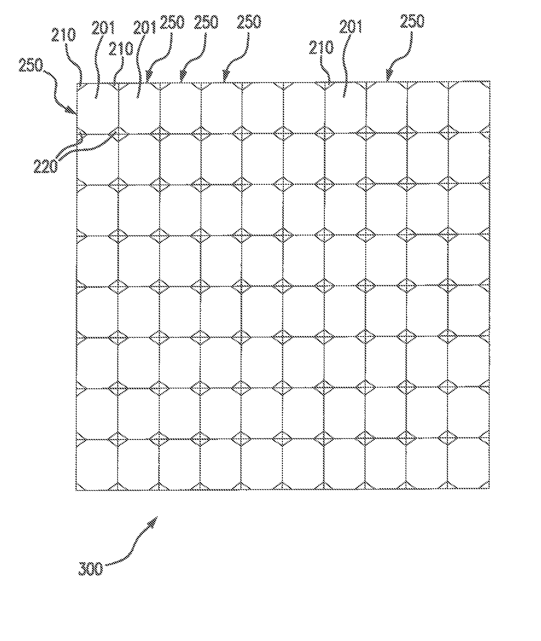
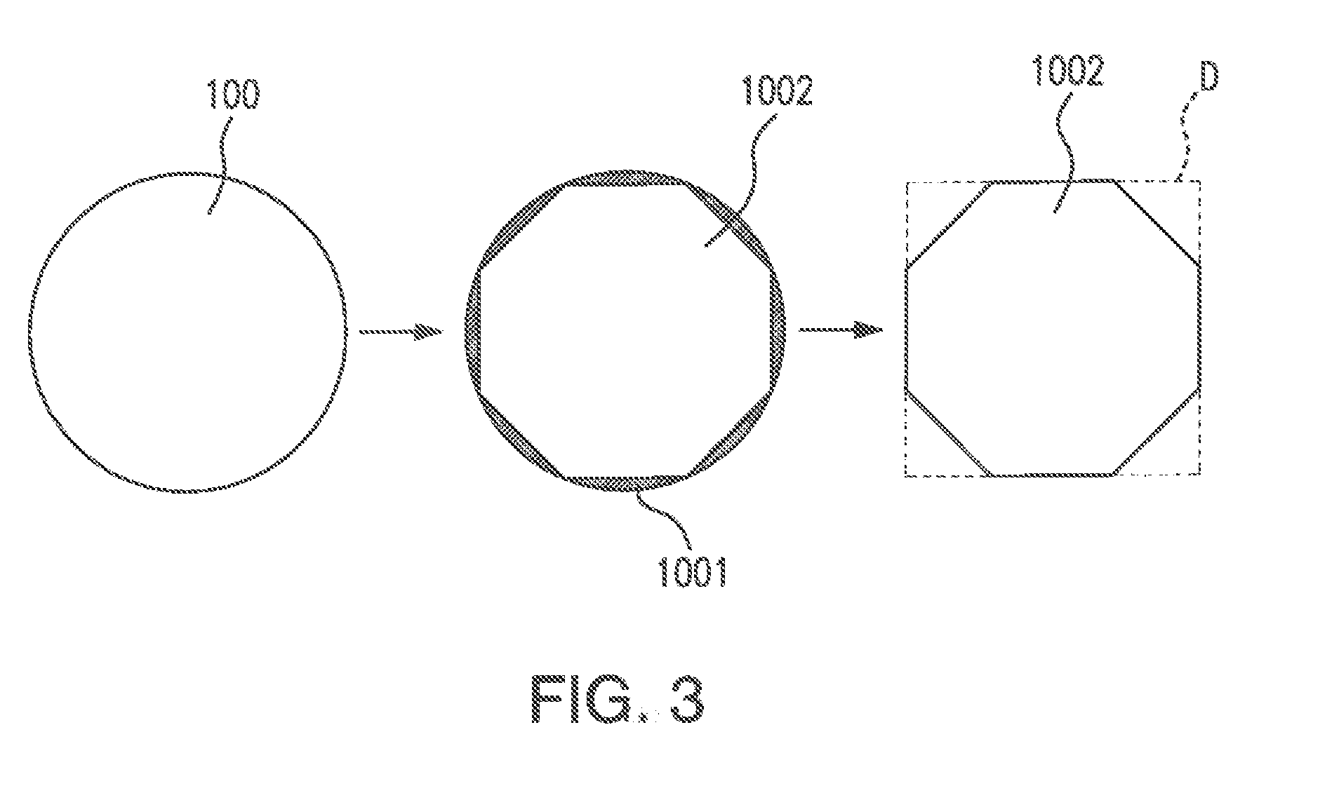
[0081]FIG. 4A schematically illustrates how 4 circular wafer 100 can be subdivided into one relatively large first solar cell 101, in this case having an octagonal shape, and a plurality of relatively small second solar cells 110, each having a substantially triangular shape. FIG. 4B schematically illustrates how the first solar cell 101 and four of the second solar cells 110 can be arranged to form a rectangular subassembly 140, in which the first solar cell 101 and the second solar cells 110 are connected in parallel, by interconnects 120 and 130. Interconnects 130 are arranged for further interconnecting the subassembly in series with another subassembly when forming a solar cell assembly out of the subassemblies. It is clear from FIGS. 4A and 4B that a high wafer utilization is achieved (as wafer material outside the first octagonal solar cell 101 is used for making the further, second, solar cells), and that a subassembly 140 with high packing factor is achieved, namely, with 1...


PUM


Abstract

Solar cells are obtained by singulating a non-rectangular solar cell wafer into a plurality of solar cells, in one embodiment a first solar cell having a surface area corresponding to at least 60% of the wafer surface area but less than 90% of the wafer surface area, and at least two second solar cells each having a surface area of less than 10% of the wafer surface area. Such a first solar cell can be connected in parallel with a plurality of the second solar cells, to establish a substantially rectangular subassembly, and such subassemblies can be combined into a larger solar cell assembly, which may be mounted on a support including other electrical components on the backside thereof, and attached to a small satellite (e.g., CubeSat) exterior surface, or deployable wing.

Description

REFERENCE TO RELATED APPLICATIONS[0001]This application claims the benefit of U.S. Provisional Patent Application No.[0002]62 / 190,441 filed Jul. 9, 2015.[0003]This application is related to U.S. Patent Application Ser. Nos. 14 / 498,071 filed Sep. 26, 2014, now U.S. Pat. No. ______ and its divisional application Ser. No. 15 / 014,667 filed Feb. 6, 2016.[0004]This application is also related to U.S. patent application Ser. No. 14 / 514,883 filed Oct. 14, 2014.[0005]This application is also related to U.S. patent application Ser. No. 14 / 151,236 filed Jan. 9, 2014.[0006]This application is also related to U.S. patent application Ser. No. 15 / 058,805 filed Mar. 2, 2016.[0007]This application is also related to U.S. Patent Application Ser. Nos. 29 / 505,800 and 29 / 505,801 filed Feb. 17, 2016.[0008]Each of the above applications are hereby incorporated by reference.BACKGROUND OF THE DISCLOSURE[0009]1. Field of the Disclosure[0010]The disclosure relates to the field of photovoltaic power devices, a...

Claims


Application Information

Patent Timeline
Patent Type & Authority Applications(United States)
IPC IPC(8): H01L31/0475B64G1/44H02S10/40
CPCH01L31/0475B64G1/443H02S10/40Y02E10/50H01L31/035281
Inventor AIKEN, DANIELCLEVENGER, MARVIN
Owner SOLAERO TECH CORP
Learn More