
Eureka
For R&D, Eureka makes reading and utilizing patents & technical documents easy.
Eureka AIR
Designed for self-driven R&D workflows. Generate viable solutions, solve complex R&D challenges, empower your innovation with AI.

Eureka Materials
Designed for material experts only. Revolutionize your material R&D, from search, analyze, to developing new materials.

TechResearch
Generate reliable direction feasibility study reports for your R&D in just a few steps.

TechSeek
Discover and master advanced knowledge NOW. Basics, ideas, possibilities, all at once.

TechMind
As an expert in R&D Theories, TechMind can generates customized viable solutions instantly.

TechRisk
Analyze your overall solution with one click, know your potential R&D risks in advance.

TechMonitor
Get weekly tech updates, stay abreast of the latest tech innovations and key insights.
Device for vascular and peritoneal access and a device for hemodialysis
- Summary
- Abstract
- Description
- Claims
- Application Information
AI Technical Summary
Benefits of technology
Problems solved by technology
Method used
Image

Examples
example 1
First Embodiment of the Device of the Invention
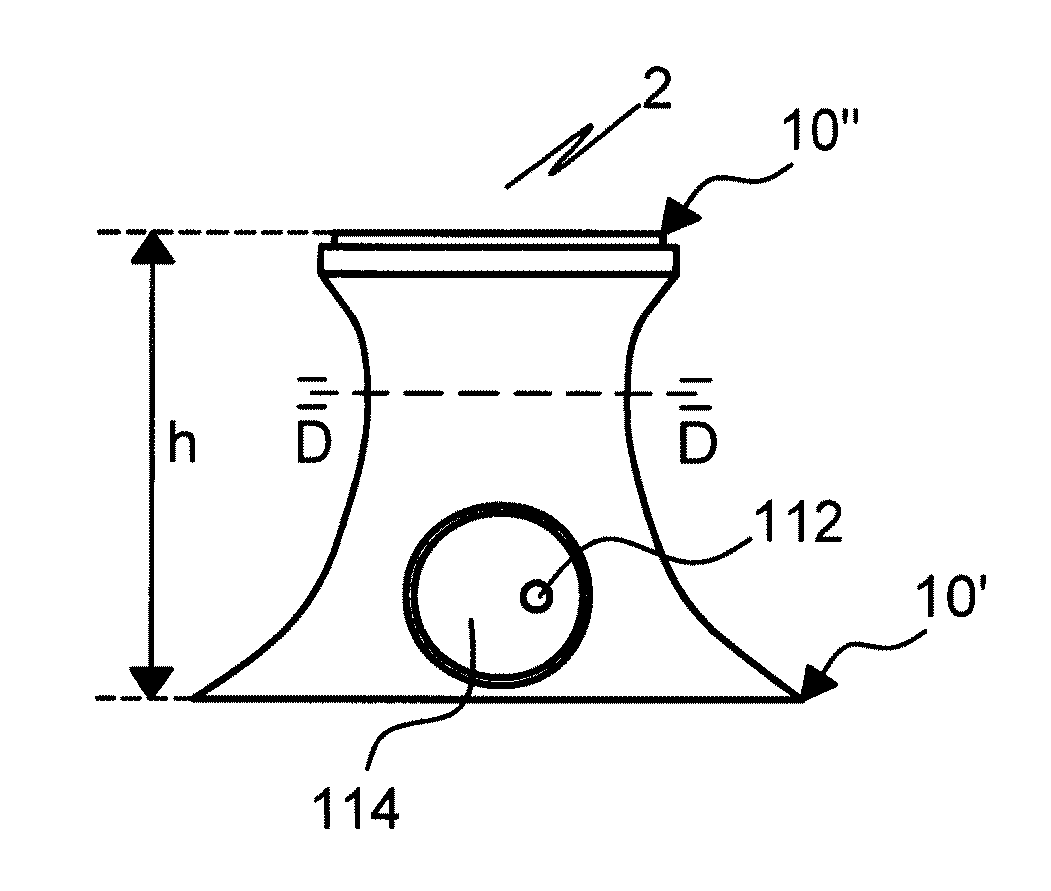
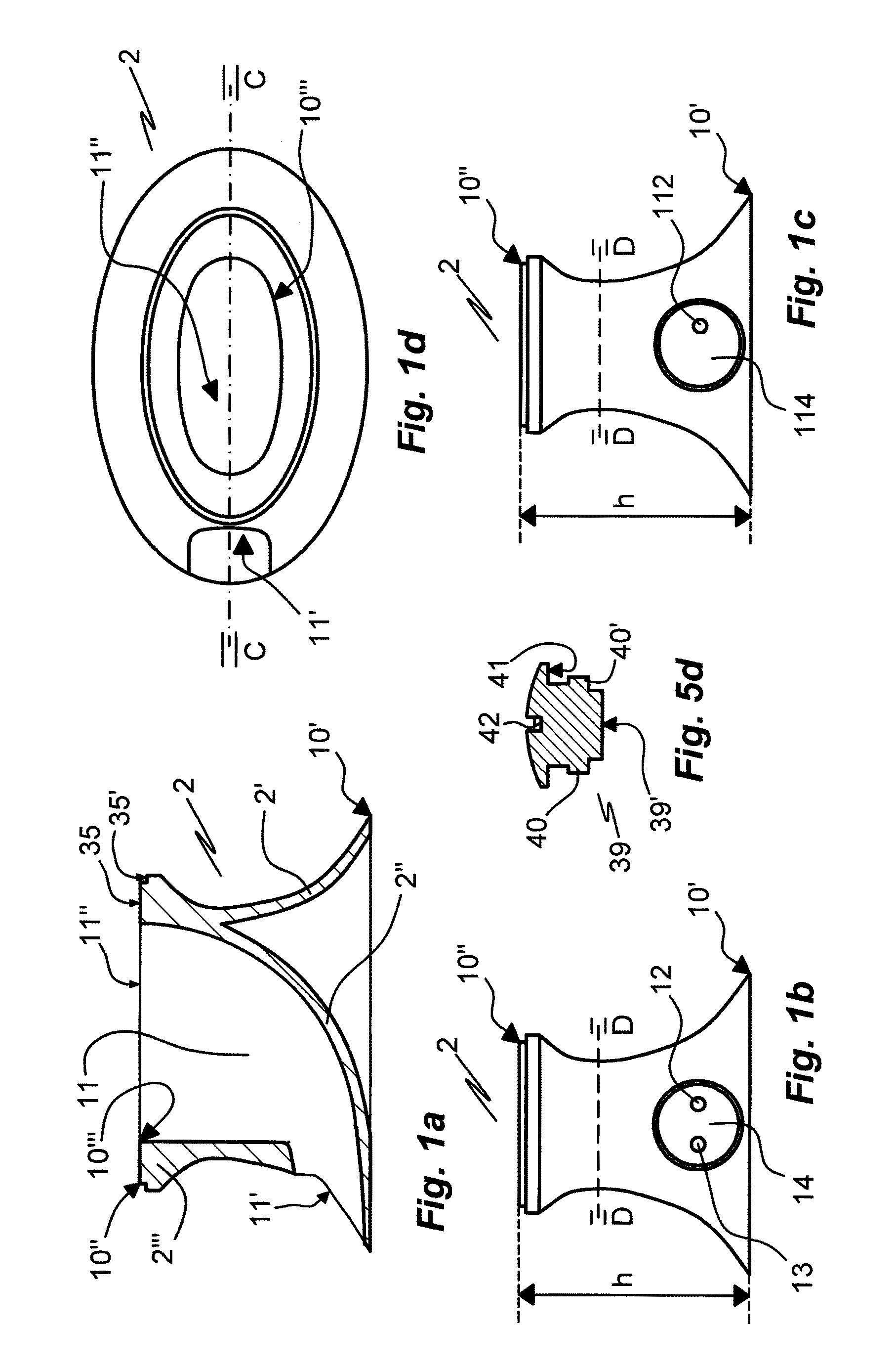
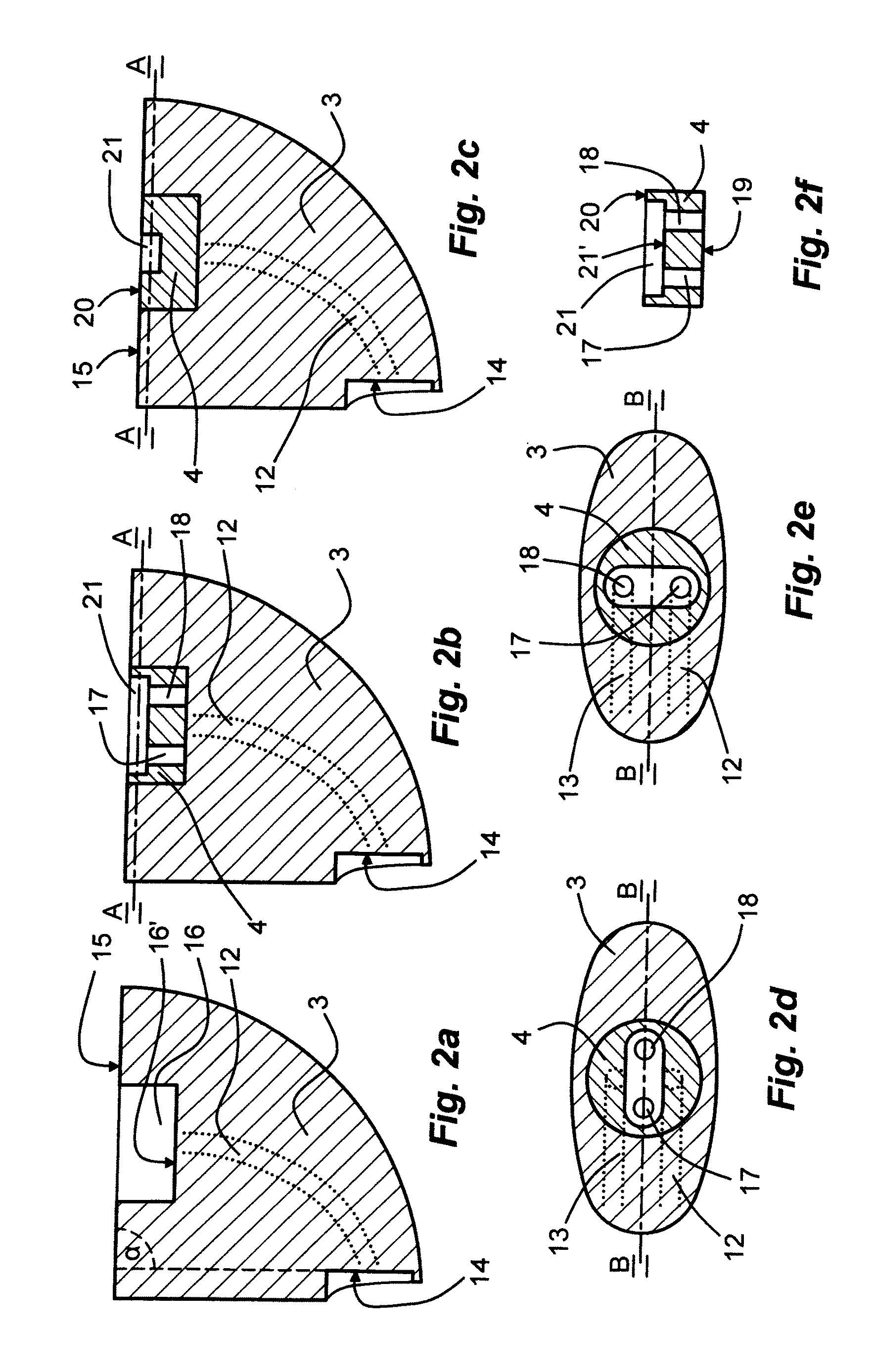
[0066]A first embodiment 1 of the venous access device of the invention relates to a device for hemodialysis (FIG. 6). The device 1 comprises a housing 2, an insert 3 disposed in a void 11 of the housing 2, and a cylindrical valve member 4 disposed in a cylindrical recess 16 of the insert. The housing 2 has about the form of a skirt 2′, which is about elliptical in radial section or a top view (FIG. 1d). The housing 2 extends between about elliptical upper 10″ (proximal) and lower 10′ (distal) circumferential rims disposed in parallel planes (FIG. 1b). Broken line D-D indicates roughly the extra-corporeal / intra-corporeal border. The interior of the housing 2 defined by the skirt 2′ and said planes is divided by an insert holding wall 2″ which, together with sections of the skirt 2′ (inner face of 2″′), defines the void 11 in which the insert 3 is disposed. The wall thickness of an elliptic upper / proximal portion 2″′ of the skirt 2′ exte...
example 2
Second Embodiment of the Device of the Invention
[0077]The second embodiment (FIG. 11) of the venous or peritoneal access device of the invention relates to a device for venous infusion or peritoneal infusion as well as peritoneal sequential infusion and drainage in peritoneal dialysis. The device 101 for venous infusion or peritoneal infusion or infusion / drainage shares all functional elements with the device for hemodialysis 1 of EXAMPLE 1 except for that its catheter is a single lumen venous or peritoneal catheter 147, 148 and that one 13, 18, 24 of the two fluid passages 12, 17, 23 and 13, 18, 24 extending between the hemodialysis catheter 47, 48 and the coupling member 5 has been omitted. In contrast to the double-channel embodiment of Example 1, the device of Example 3 is a single-channel venous access device. It can be used, for instance, for infusion of aqueous solutions or suspensions comprising pharmaceuticals and / or nutrients and / or salts. Elements of same function in the ...
example 3
Variety of the Housing of the Device According to the Invention
[0079]The third embodiment of the invention relates to a housing 102′ variety, FIG. 7, which can be substituted for the housing 2, 102 of the first and second embodiment of the device of the invention. The lower portion of the housing 102′ is provided with a number of slits 150 extending in a circumferential direction. Also provided are a number of through bores 151 arranged near the distal skirt of the housing 102′. The bores 151 are provided to allow attachment of the housing 102′ to surrounding tissue by means of suture. On a circumferential proximal flat face are disposed four threaded bores 152 for mounting of a cover 107′ (FIG. 8) by means of screws. The cover 107′ comprises an integral rotation restricting element 106′ of a design corresponding to that of element 6, 106 of the first and third embodiments. Reference numbers indicate: 135, a central bore; 128, 129, diametrically opposite, axially extending grooves i...
PUM
 Abstract
Description
Claims
Application Information
 - R&D Engineer
- R&D Manager
- IP Professional
- Industry Leading Data Capabilities
- Powerful AI technology
- Patent DNA Extraction
Browse by: Latest US Patents, China's latest patents, Technical Efficacy Thesaurus, Application Domain, Technology Topic, Popular Technical Reports.
© 2024 PatSnap. All rights reserved.Legal|Privacy policy|Modern Slavery Act Transparency Statement|Sitemap|About US| Contact US: help@patsnap.com