Vehicle control device

a technology of vehicle control and control device, which is applied in the direction of electric devices, brake components, braking systems, etc., can solve the problems of insufficient braking force, ineffective use of rotational energy of wheels, and limited braking force that can be generated by electric power regeneration. achieve the effect of regeneration enhancement control

Active Publication Date: 2017-01-19
TOYOTA JIDOSHA KK
View PDF4 Cites 16 Cited by
  • Summary
  • Abstract
  • Description
  • Claims
  • Application Information

AI Technical Summary

Benefits of technology

[0031]The accelerator release guidance means is configured to give the notification for prompting the driver to release the accelerator pedal so that the deceleration of the vehicle finishes at the target deceleration end position. In other words, a release timing for the accelerator pedal is notified to the driver. When the driver follows the guidance by the accelerator release guidance means to release the accelerator pedal, the regeneration enhancement control is carried out. Thus, the ecological drive by the driver is more appropriately supported.
[0032]Incidentally, when the vehicle is highly likely to collide with an obstacle, it is necessary to cause the driver to operate the brake pedal as soon as possible. For examp

Problems solved by technology

There is an upper limit for a charge current that can be supplied to a battery, and hence, on the vehicle including the regenerative generator, a braking force that can be generated by the electric power regeneration is also limited.
Upon an emergency braking operation, a required braking force temporarily exceeds the braking force that can be generated by the electric power regeneration, and hence an insufficient amount in the braking force is compensated by a hydraulic friction braking.
Thus, a rotational energy of the wheels cannot be used effectively.
Thus, the emergency braking operation by the driver can be suppressed, and the power can thus be efficiently recovered to the battery, resulting in an increase in fuel consumption performance.
In this case, the regeneration enhancement control is finished when the own vehicle passes the target

Method used


Image

  • Vehicle control device
  • Vehicle control device
  • Vehicle control device

Examples


Embodiment Construction

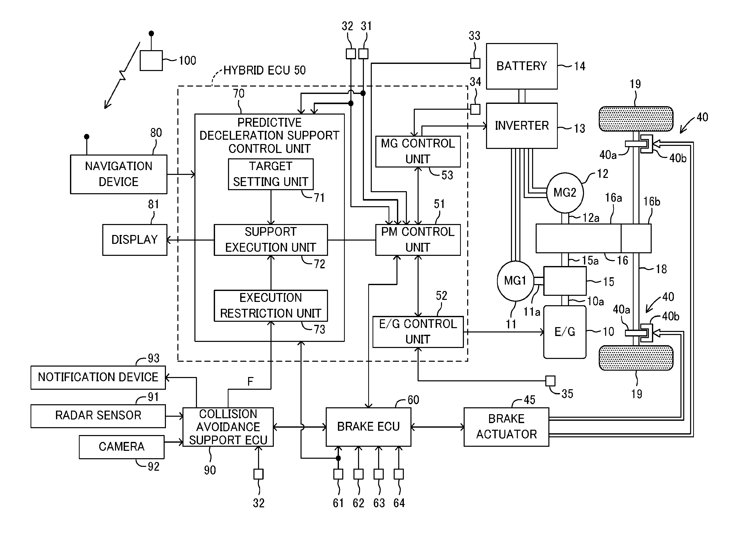
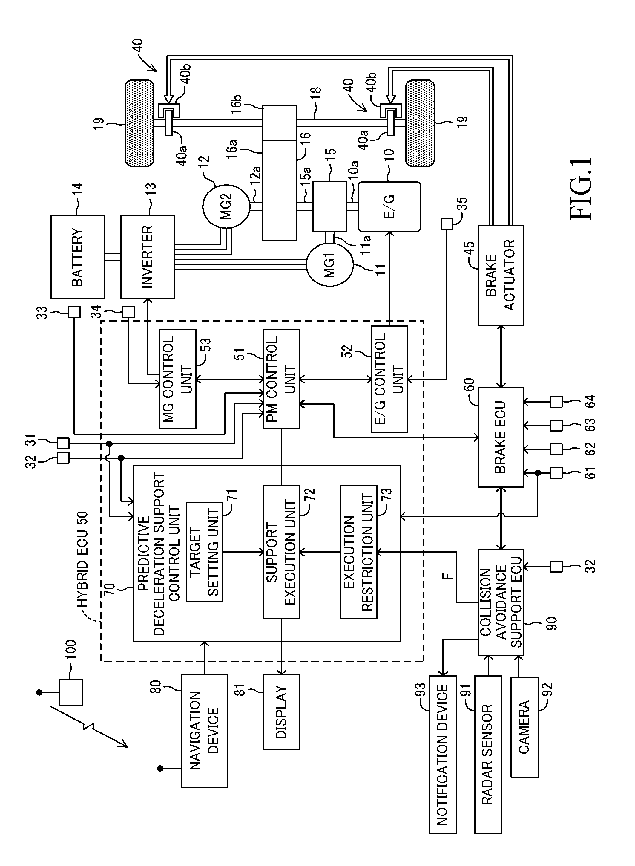
[0043]Referring to the accompanying drawings, an embodiment of the present invention is described in detail below. FIG. 1 is a schematic system configuration diagram for illustrating a vehicle control device according to an embodiment of the present invention.

[0044]A vehicle on which the vehicle control device according to this embodiment is installed is a hybrid vehicle. This vehicle includes an engine 10, a first motor generator 11 (referred to as first MG 11), a second motor generator 12 (referred to as second MG 12), an inverter 13, a battery 14, a power distribution mechanism 15, a driving force transmission mechanism 16, and a hybrid electronic control unit 50 (referred to as hybrid ECU 50) as a travel drive device.

[0045]The engine 10 is a gasoline engine or a diesel engine.

[0046]The power distribution mechanism 15 is configured to distribute a driving force of the engine 10 to power for driving an output shaft 15a of the power distribution mechanism 15 and power for driving t...


PUM


Abstract

Appropriate collision avoidance support control is enabled in a vehicle configured to carry out regeneration enhancement control. A predictive deceleration support control unit is configured to set a position at which the vehicle is predicted to finish deceleration as a target deceleration end position, and guide a driver to release an accelerator pedal so that the deceleration of the vehicle is finished at the target deceleration end position, to thereby carry out regeneration enhancement control under a state in which the accelerator pedal is released so as to generate a larger deceleration than in a normal state. The predictive deceleration support control unit is configured to read a collision avoidance support control flag from a collision avoidance support ECU, and stop the regeneration enhancement control when the collision avoidance support control is being carried out.

Description

BACKGROUND OF THE INVENTION[0001]1. Field of the Invention[0002]The present invention relates to a vehicle control device, which is configured to support an operation of a driver so as to increase an electric power regeneration amount in a vehicle capable of generating a braking force by recovering electric power to an in-vehicle battery.[0003]2. Description of the Related Art[0004]For example, as proposed in International Patent WO2012 / 053106A1, there is known a drive support device, which is configured to set a target stop position for a vehicle and to issue an instruction to release an accelerator pedal so that the vehicle stops at the target stop position. Moreover, as proposed in Japanese Patent Application Laid-open No. 2015-19521, there is known a vehicle including a regenerative generator, which is configured to set such a deceleration start position as to increase an electric power regeneration amount to be recovered to a battery during deceleration travel up to a target st...

Claims


Application Information

Patent Timeline
IPC IPC(8): B60L7/18B60T7/12B60T8/171B60L15/20B60L50/15B60L50/16
CPCB60L7/18B60L15/2009B60Y2200/92B60T8/171B60L2240/12B60T7/12B60W10/188B60W30/09B60W40/02B60W50/14B60W2050/143B60W2050/146B60W2710/182B60W2554/00B60T1/10B60T13/586F16D61/00B60L3/0015B60L2240/423B60L2250/28B60T2201/022B60T2270/604Y02T10/72B60L50/62B60L50/16Y02T10/62Y02T10/64Y02T10/7072Y02T10/70
Inventor OGURI, HARUKI
Owner TOYOTA JIDOSHA KK
Why Eureka
Try Eureka