On the fly automatic wafer centering method and apparatus

a technology of automatic wafer centering and wafer centering, which is applied in the direction of electric devices, conveyor parts, transportation and packaging, etc., can solve the problems of reducing production time, generating particles (e.g. contamination) within the substrate processing equipment, and operating errors

Active Publication Date: 2017-01-19
BOOKS AUTOMATION US LLC
View PDF18 Cites 29 Cited by
  • Summary
  • Abstract
  • Description
  • Claims
  • Application Information

AI Technical Summary

Problems solved by technology

The manual placement of the substrate centering fixture and the manual placement of the substrate relative to the substrate centering fixture may result in operator errors and the generation of particles (e.g. contamination) within the substrate processing equipment.
The use of substrate centering fixtures also is performed at atmosphere which means that the environment within the substrate processing equipment is disturbed thereby reducing production time.
These approaches to teaching locations within substrate processing equipment may require sensors being placed in a vacuum, may require changes to customer processing equipment and / or tooling, may not be suitable for use in vacuum environments or at high temperatures, may require sensor targets, mirrors or fixtures being placed within the processing equipment, may disrupt a vacuum environment of the substrate processing equipment, and / or may require software changes to the code embedded into the substrate transport robot's and / or processing system's controller.
Generally, the limitation of the conventional arm temperature compensation algorithms is that they do not accurately compensate for position errors for the case where the manipulator links are under temperature transients such as temperature rise or cool down.
These conventional thermal compensation algorithms also generally do not take into account the non-linear effect of the arm kinematics due to their non-linear sensitivity to link angular location with respect to the end effector position.

Method used


Image

  • On the fly automatic wafer centering method and apparatus
  • On the fly automatic wafer centering method and apparatus
  • On the fly automatic wafer centering method and apparatus

Examples


Embodiment Construction

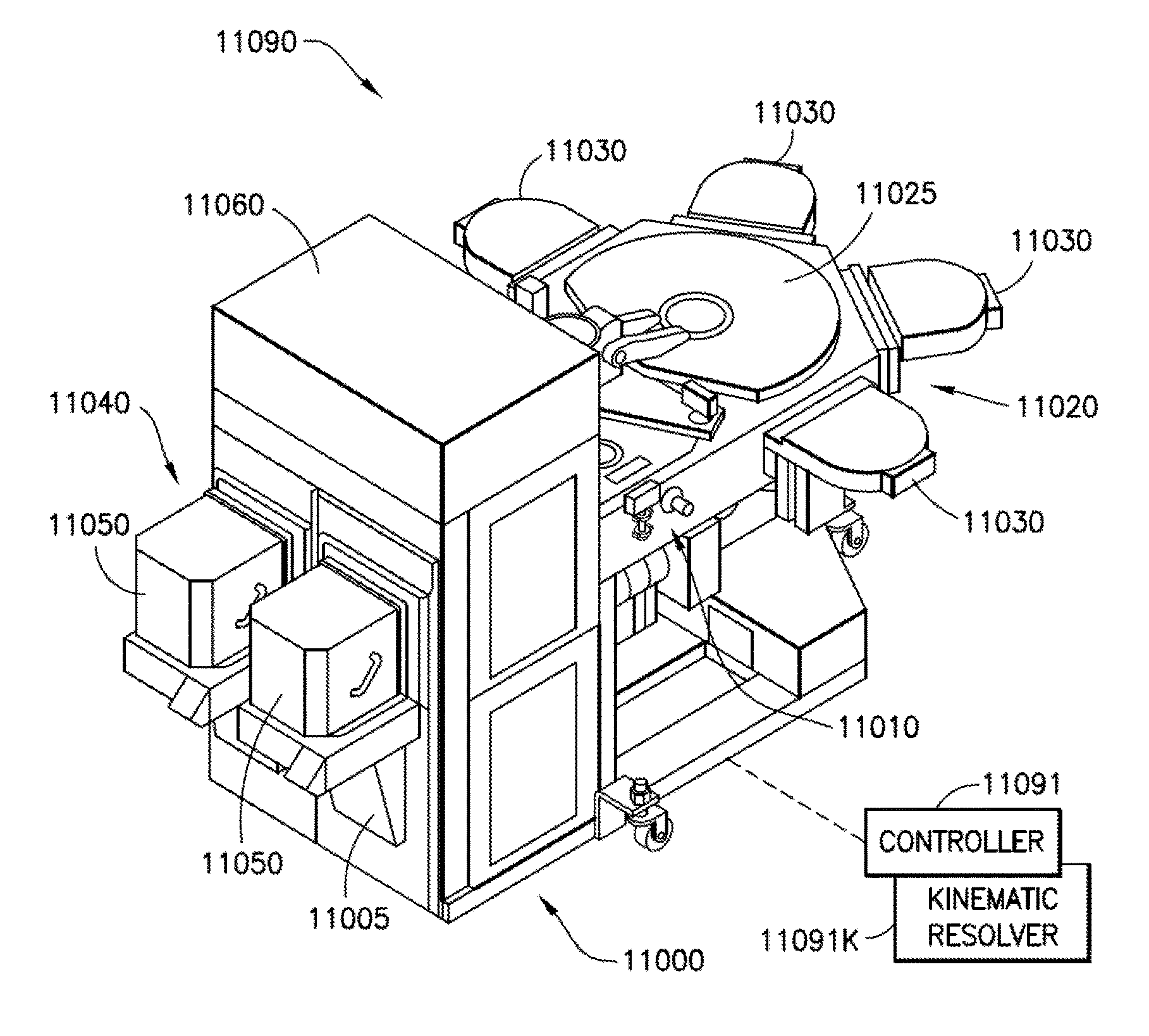
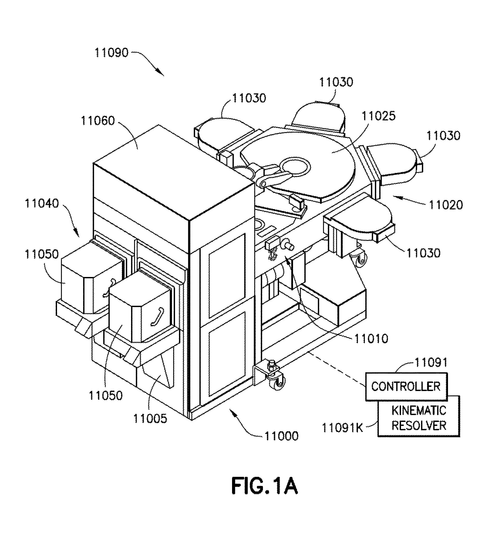
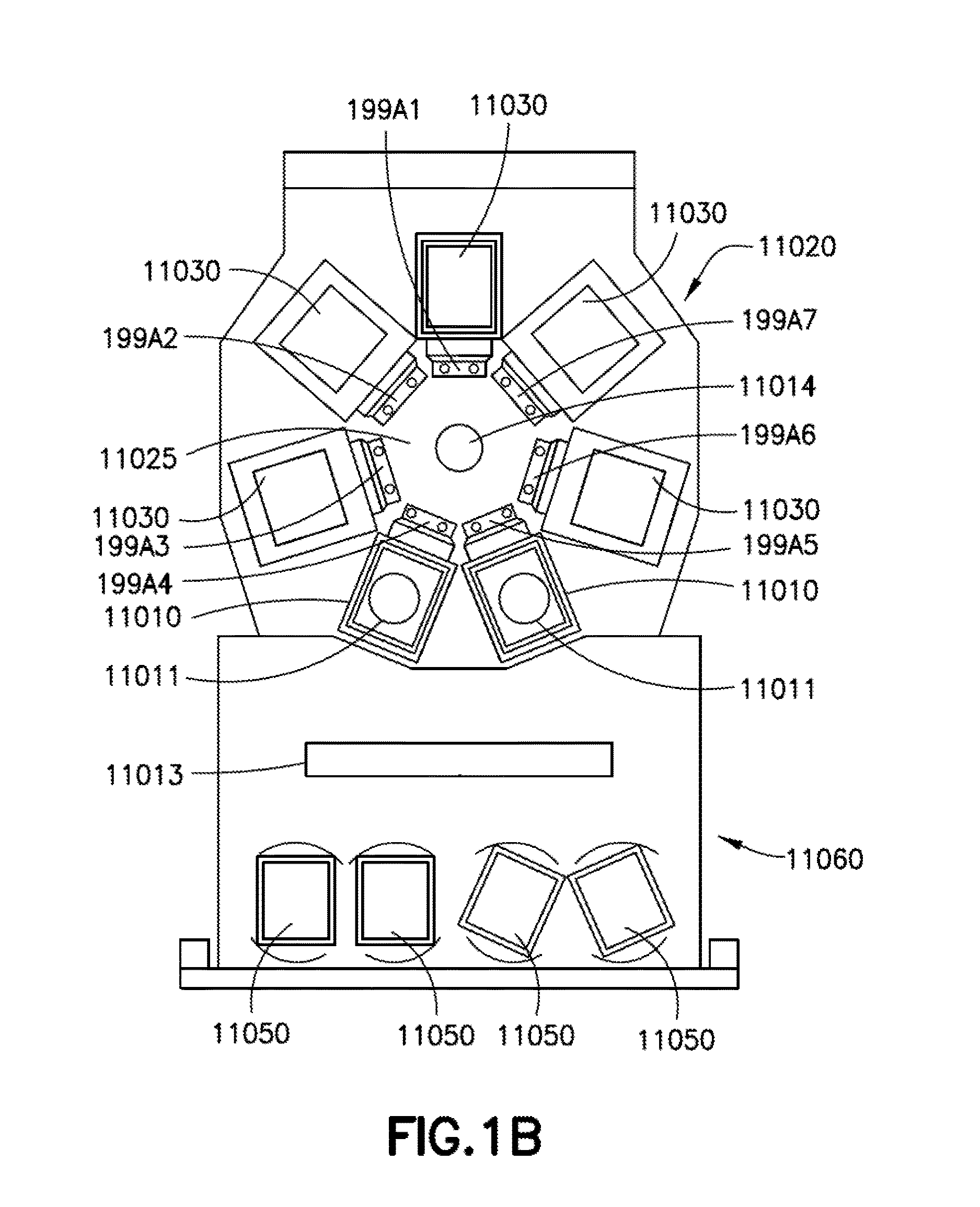
[0044]Referring to FIGS. 1A-1D, there are shown schematic views of substrate processing apparatus or tools incorporating the aspects of the disclosed embodiment as will be further described herein. Although the aspects of the disclosed embodiment will be described with reference to the drawings, it should be understood that the aspects of the disclosed embodiment can be embodied in many forms. In addition, any suitable size, shape or type of elements or materials could be used.

[0045]As will be described in greater detail below, the aspects of the disclosed embodiment provide for the automatic (e.g. without operator intervention) centering of substrates or wafers relative to, for example, a substrate transport end effector, the automatic location of substrate holding stations of a substrate processing apparatus, and teaching a substrate transport apparatus the locations of the substrate holding stations. It is noted that the terms substrate and wafer are used interchangeably herein. ...


PUM


Abstract

Substrate processing apparatus including a wafer transport apparatus with a transport arm including an end effector, an arm pose deterministic feature integral to the substrate transport apparatus and disposed so that a static detection sensor of the substrate processing apparatus detects at least one edge of the at least one arm pose deterministic feature on the fly with radial motion of the transport arm, and a controller configured so that detection of the edge effects a determination of a proportion factor identifying at least a thermal expansion variance of the transport arm on the fly and includes a kinematic effects resolver configured to determine, from the detection of the edge on the fly, a discrete relation between the determined proportion factor and each different discrete variance respective to each different link of the transport arm determining at least the thermal expansion variance of the transport arm on the fly.

Description

CROSS-REFERENCE TO RELATED APPLICATIONS[0001]This application is a non-provisional of and claims the benefit of U.S. provisional patent application No. 62 / 191,863 filed on Jul. 13, 2015 and U.S. provisional patent application No. 62 / 320,142 filed on Apr. 8, 2016, the disclosures of which are incorporated herein by reference in their entireties.BACKGROUND[0002]1. Field[0003]The exemplary embodiments generally relate to substrate processing systems and, more particularly, to calibration and synchronization of components of the substrate processing systems.[0004]2. Brief Description of Related Developments[0005]Substrate processing equipment is typically capable of performing multiple operations on a substrate. The substrate processing equipment generally includes a transfer chamber and one or more process modules coupled to the transfer chamber. A substrate transport robot within the transfer chamber moves substrates among the process modules where different operations, such as sputte...

Claims


Application Information

Patent Timeline
Patent Type & Authority Applications(United States)
IPC IPC(8): H01L21/677H01L21/67H01L21/68H01L21/687
CPCH01L21/67706H01L21/68785H01L21/68H01L21/67167H01L21/67173H01L21/68707H01L21/67742H01L21/682
Inventor YIN, BINGMOURA, JAIRO T.TSANG, VINCENTGAWLIK, AARONSPIKER, NATHAN
Owner BOOKS AUTOMATION US LLC
Why Eureka
Try Eureka