
Signal amplifying circuit with noise suppression function

a signal amplifying circuit and function technology, applied in the direction of amplifiers, amplifier modifications to reduce noise influence, amplifiers with semiconductor devices/discharge tubes, etc., can solve the problems of high energy consumption of conventional chopping amplifiers, high manufacturing cost, and high material and manufacturing cost, so as to reduce the interior frequency bandwidth of signals, effectively suppress chopping interference, and reduce current consumption. the effect of power consumption

Active Publication Date: 2017-01-19
PIXART IMAGING INC
View PDF0 Cites 0 Cited by
  • Summary
  • Abstract
  • Description
  • Claims
  • Application Information

AI Technical Summary

Benefits of technology

The present invention provides a signal amplifying circuit that can effectively suppress noise by low speed of electric charge / discharge. The circuit decreases the current volume or increases the equivalent capacitance to reduce the interior frequency bandwidth, which eliminates direct current offset voltage and low frequency noise. The circuit is driven in slew rate, which reduces the interior frequency bandwidth and avoids current consumption. The circuit can effectively suppress chopping interference and allows for processing signals without linearity effect even without an analog filter. Overall, the invention improves the quality of the signal amplification process.

Problems solved by technology

An interior frequency bandwidth of the conventional chopping amplifier is greater than the chopping frequency to avoid insufficient settling time, and the chopping frequency has to be greater than signal frequency according to manufacture of the low-pass filter, so the conventional chopping amplifier has a drawback of high energy consumption.
Besides, the low-pass filter of the conventional chopping amplifier is an internal capacitance of the circuit or an independent capacitance outside the circuit, which spends expensive material and manufacturing cost.

Method used


Image

  • Signal amplifying circuit with noise suppression function
  • Signal amplifying circuit with noise suppression function
  • Signal amplifying circuit with noise suppression function

Examples


Embodiment Construction

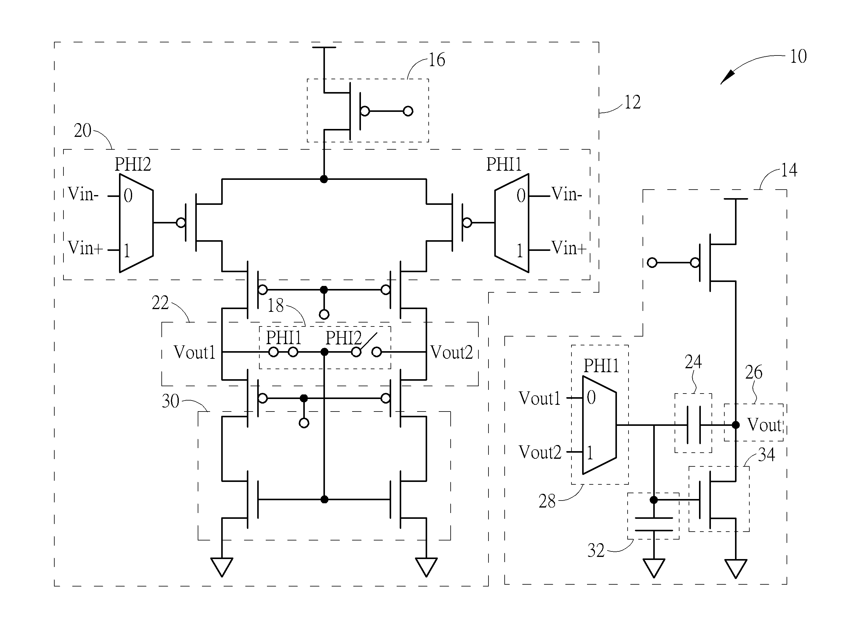
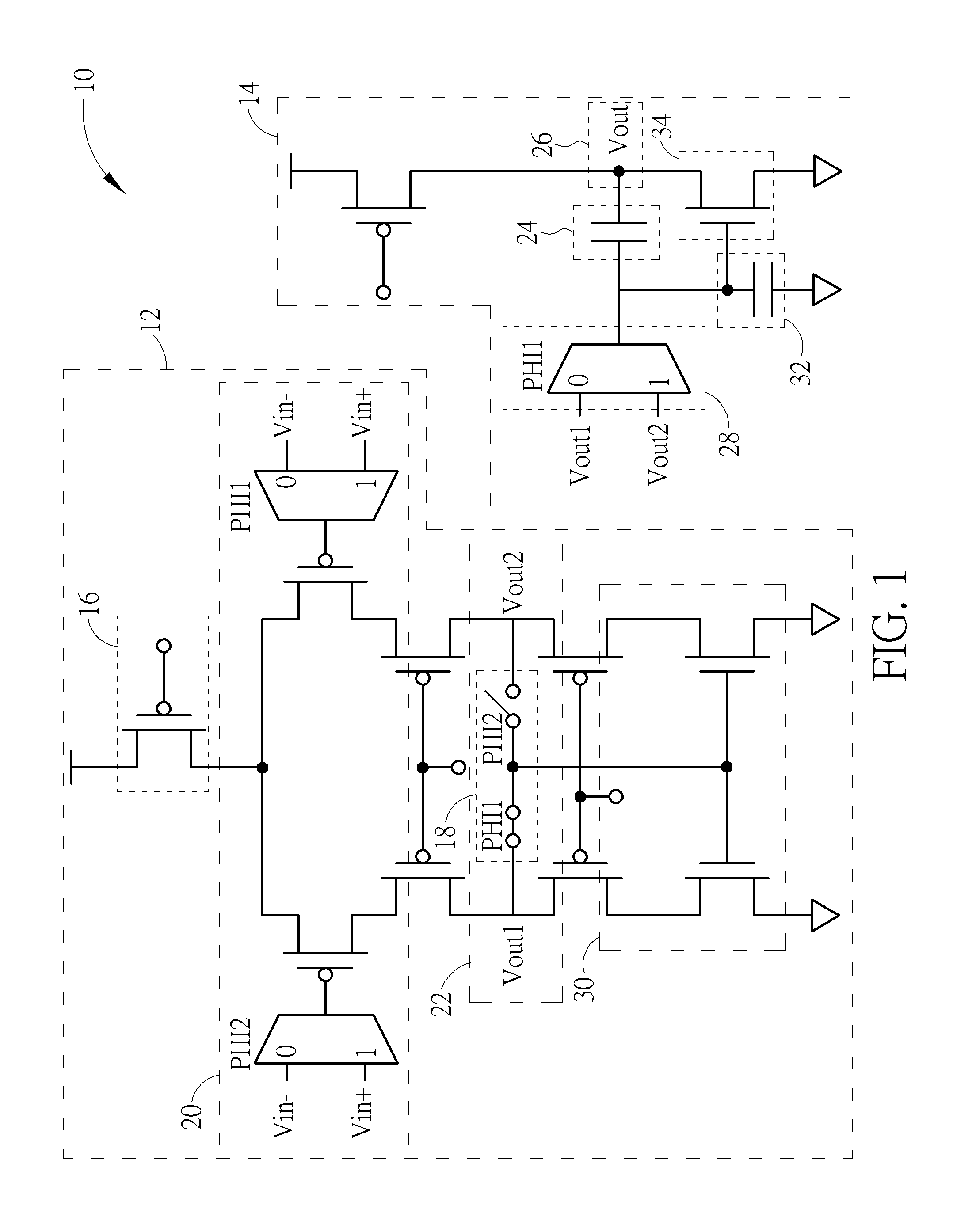
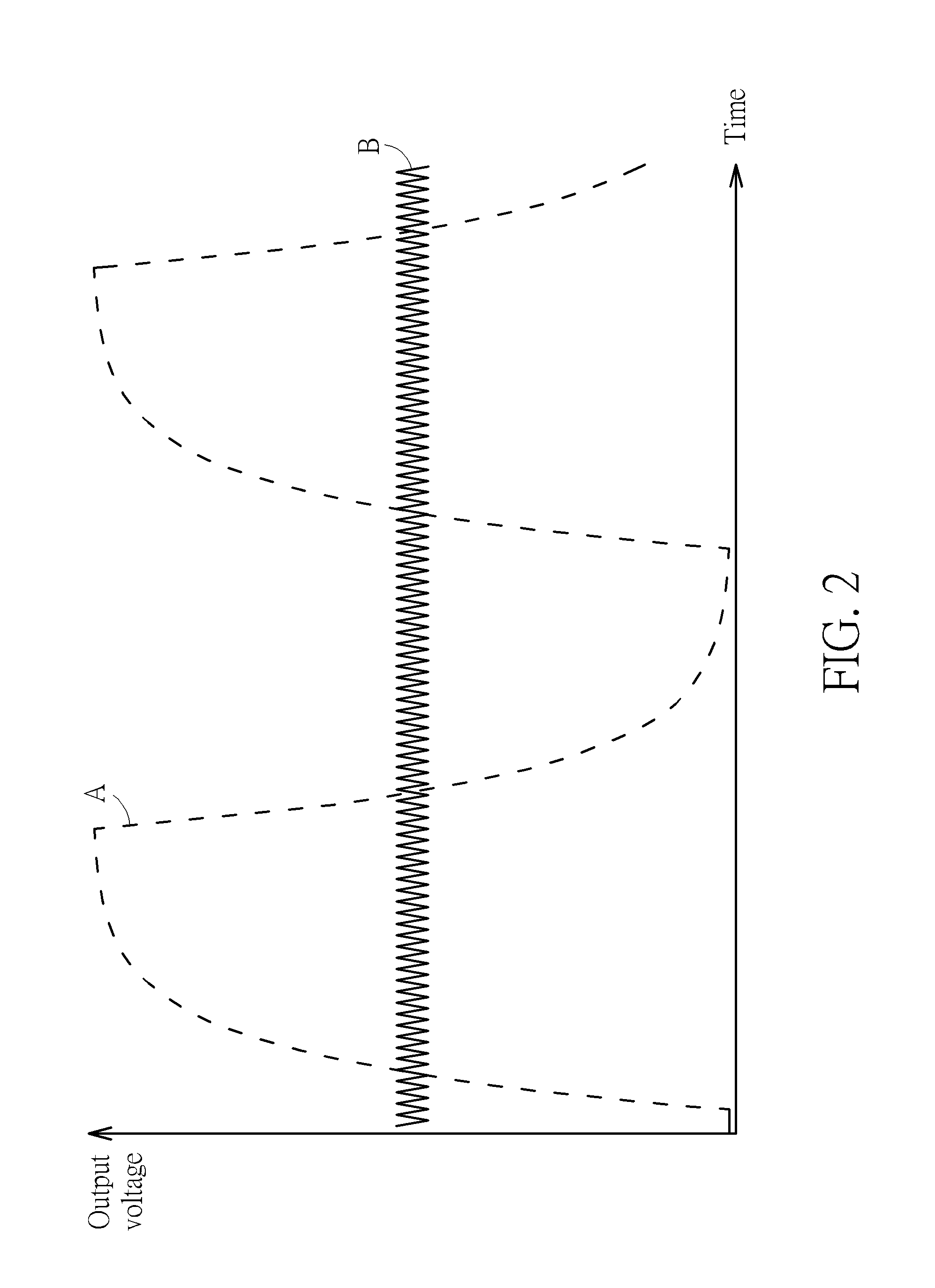
[0016]Please refer to FIG. 1. FIG. 1 is a diagram of a signal amplifying circuit 10 with noise suppression function according to an embodiment of the present invention. A conventional amplifier circuit is rapidly changed from high to low and outputs square chopping wave with large amplitude. For overcoming interference of the chopping wave effectively, the signal amplifying circuit 10 of the present invention can conspicuously suppress speed of electric charge / discharge, constraint of slew rate is utilized to transform its outputting wave into triangular wave with low amplitude, and interference amplitude can be effectively decreased, so that another circuit back the signal amplifying circuit 10 is no need of wide range of the input voltage and design of an extra filter.

[0017]The signal amplifying circuit 10 is mainly composed of a first circuit module 12 and a second circuit module 14. A buffer circuit can be optionally disposed between the first circuit module 12 and the second ci...


PUM


Abstract

A signal amplifying circuit with noise suppression function includes a first circuit module and a second circuit module. The first circuit module includes a current source and a switch. The current source is connected to an input stage for inputting a current. The switch is connected to a first output terminal and adapted to switch the input stage and the first output terminal according to a chopping frequency. The second circuit module includes an equivalent capacitance disposed between an output stage and a second input terminal connected to the first output terminal. The signal amplifying circuit controls current volume of the current source and capacity value of the equivalent capacitance to accordingly adjust an interior frequency bandwidth of the signal amplifying circuit, and the interior frequency bandwidth is smaller than the chopping frequency and greater than an input signal of the input stage.

Description

BACKGROUND OF THE INVENTION[0001]1. Field of the Invention[0002]The present invention relates to a signal amplifying circuit, and more particularly, to a signal amplifying circuit capable of effectively suppressing noise by low speed of electric charge / discharge.[0003]2. Description of the Prior Art[0004]Chopping technology utilizes the switch to change orientation of the direct current (DC) offset and the low frequency noise relative to the signal, the direct current offset and the low frequency noise are transformed into high frequency interference, and the low-pass filter can be applied to eliminate the interference accordingly. An interior frequency bandwidth of the conventional chopping amplifier is greater than the chopping frequency to avoid insufficient settling time, and the chopping frequency has to be greater than signal frequency according to manufacture of the low-pass filter, so the conventional chopping amplifier has a drawback of high energy consumption. Besides, the...

Claims


Application Information

Patent Timeline
Patent Type & Authority Applications(United States)
IPC IPC(8): H03F1/26H03F3/217
CPCH03F1/26H03F2200/372H03F2200/351H03F3/2171H03F3/393H03F3/45188
Inventor HWANG, HSIANG-WEICHIU, JUI-TE
Owner PIXART IMAGING INC
Learn More