Batch change control for variable speed driven centrifugal pumps and pump systems

a technology of variable speed driven centrifugal pumps and pump systems, which is applied in the direction of radial flow pumps, mechanical equipment, machines/engines, etc., can solve problems such as hydraulic and power disturbances

Inactive Publication Date: 2017-02-02
SIEMENS AG
View PDF10 Cites 22 Cited by
  • Summary
  • Abstract
  • Description
  • Claims
  • Application Information

AI Technical Summary

Benefits of technology

[0007]Briefly described, aspects of the present invention relate to a method and systems for batch change control for variable speed-driven centri

Problems solved by technology

But there are hydraulic and power disturbances when heavy-to-l

Method used


Image

  • Batch change control for variable speed driven centrifugal pumps and pump systems
  • Batch change control for variable speed driven centrifugal pumps and pump systems
  • Batch change control for variable speed driven centrifugal pumps and pump systems

Examples


Embodiment Construction

[0016]In order to facilitate an understanding of embodiments, principles, and features of the present invention, these are explained hereinafter with reference to implementation in illustrative embodiments. In particular, these are described in the context of being methods and systems for a batch change control for variable speed driven centrifugal pumps and pump systems. Embodiments of the present invention, however, are not limited to use in the described devices or methods.

[0017]The components and materials described hereinafter as making up the various embodiments are intended to be illustrative and not restrictive. Many suitable components and materials that would perform the same or a similar function as the materials described herein are intended to be embraced within the scope of embodiments of the present invention.

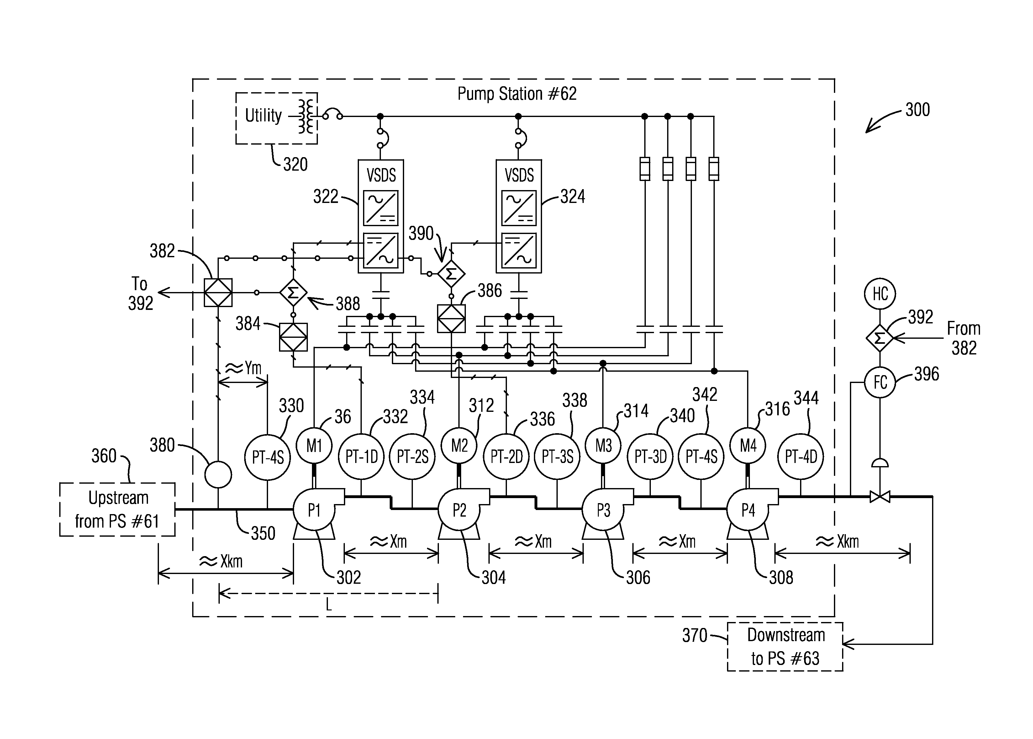
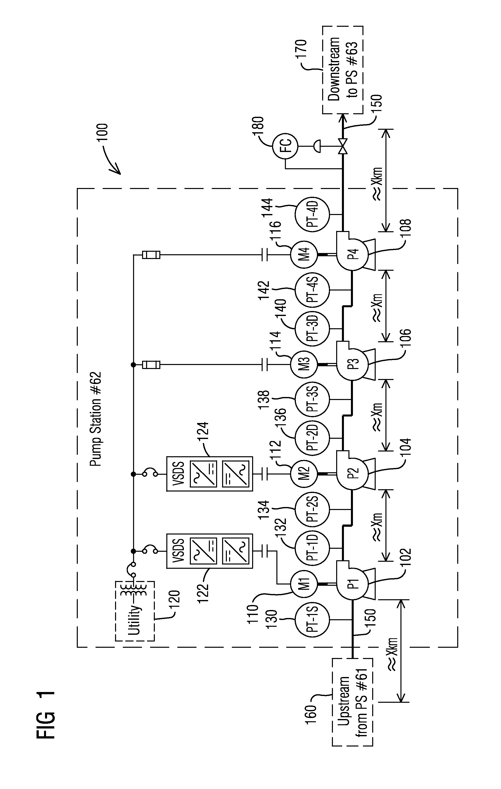
[0018]FIG. 1 illustrates an example pump station constructed in accordance with an exemplary embodiment of the present invention.

[0019]The pump station 100 as il...


PUM


Abstract

A pump system includes an interface detection meter arranged at a pipeline assembly, a drive assembly for controlling speed of a pump arranged at the pipeline assembly, a discharge pressure control assembly and/or flow control assembly for controlling discharge pressure of the pump system, and a control assembly operably coupled to the drive assembly and/or the discharge pressure control assembly and/or the flow control assembly. A logic control of the control assembly receives fluid data of fluid in the pipeline assembly provided by the interface detection meter, and forwards the fluid data for calculating speed set points for the drive assembly and/or discharge pressure control parameter and/or set points for the discharge pressure control assembly, and/or flow rate control set points for the flow control assembly. A method for controlling variable speed driven pumps or pump systems during batch change and an embodiment of a plug-and-play device are disclosed.

Description

BACKGROUND[0001]1. Field[0002]Aspects of the present invention generally relate to a method and systems for batch change control for variable speed-driven centrifugal pumps and pump systems.[0003]2. Description of the Related Art[0004]Pumps and pump systems are operated in applications for different media types, for example fluids, slurries, etc., and for different batches, generally in the process industry, and in particular in the oil and gas industry, for example pipelines, refineries, tank farms, etc. Typical oil pipelines transport batches of different types of oil. Such batches include light weight oils and heavy weight oils such as for example light crude oil, diluted bitumen oil, and synthetic crude oil with wide ranges of relative densities and viscosities. Batches can be of different products and of different grades of the same product. Batch changes can occur frequently as often as several times per day.[0005]There are different methods used to separate oil batches, for e...

Claims


Application Information

Patent Timeline
IPC IPC(8): F04D15/00F17D3/03F04D13/06F04D1/06F04D7/04
CPCF04D15/0066F04D1/06F17D3/03F04D13/06F04D7/04F04D27/0261F17D1/14F17D3/05Y02B30/70
Inventor FOWLER, EDWARD A.KLOPPNER, GERDSEENIRAJ, GANESH KUMARRHOTE-VANEY, RAPHAEL
Owner SIEMENS AG
Why Eureka
Try Eureka