Detection head of spectrophotometer

A spectrophotometer and detection head technology, applied in spectrometry/spectrophotometry/monochromator, optical radiation measurement, measuring device, etc., can solve the problems of measurement inconvenience, achieve compact structure, improve sensitivity, reduce Effect of Optics Adjustment Difficulty

Inactive Publication Date: 2011-08-03
XIAMEN UNIV
View PDF2 Cites 7 Cited by
  • Summary
  • Abstract
  • Description
  • Claims
  • Application Information

AI Technical Summary

Problems solved by technology

There are one output fiber bundle and one return fiber bundle in the special-shaped optical fiber transmission beam, and two reference fiber bundles. Up to four fibers are needed in total. The measuring probe is placed in a stainless steel tube with a length of 200mm, which largely gives the measurement zone Inconvenience

Method used


Image

  • Detection head of spectrophotometer
  • Detection head of spectrophotometer
  • Detection head of spectrophotometer

Examples


Embodiment 1

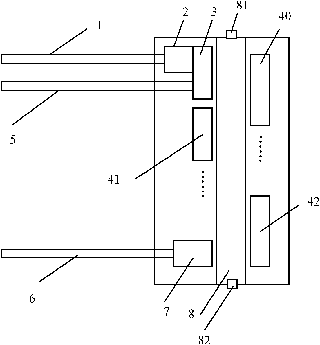
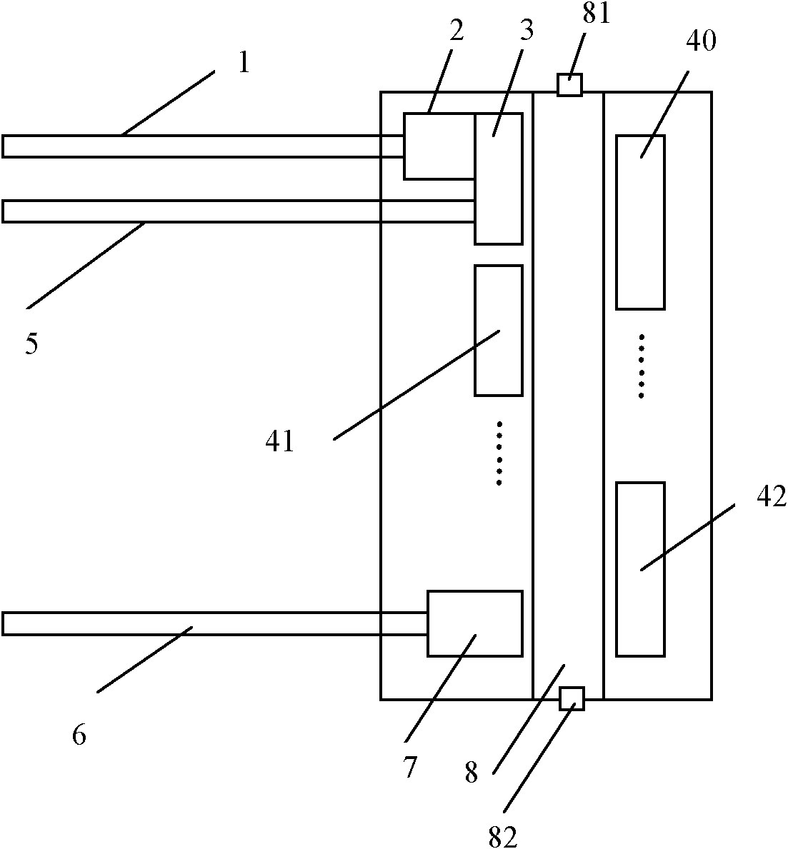
[0047] See eg figure 1 , the present invention is provided with incident optical fiber 1, incident optical fiber collimator 2, optical fiber coupler 3 (light splitter), reference optical fiber 5, return optical fiber 6, return optical fiber collimator 7, sample chamber 8 and tapered reflector prism 40, 41 and 42.

[0048] The input end of the incident fiber 1 is connected to an external light source, the output end of the incident fiber 1 is connected to the input end of the incident fiber collimator 2, the incident light is collimated by the incident fiber collimator 2, and the output light is split into two paths by the fiber coupler 3 , one of which enters the reference optical fiber 5 as reference light, and the other enters the sample chamber 8 as information light. In the sample chamber 8, the information light is reflected by the conical reflective prisms 40, 41 and 42 and passes through the sample multiple times, and enters the return fiber collimator 7 after being ab...

Embodiment 2

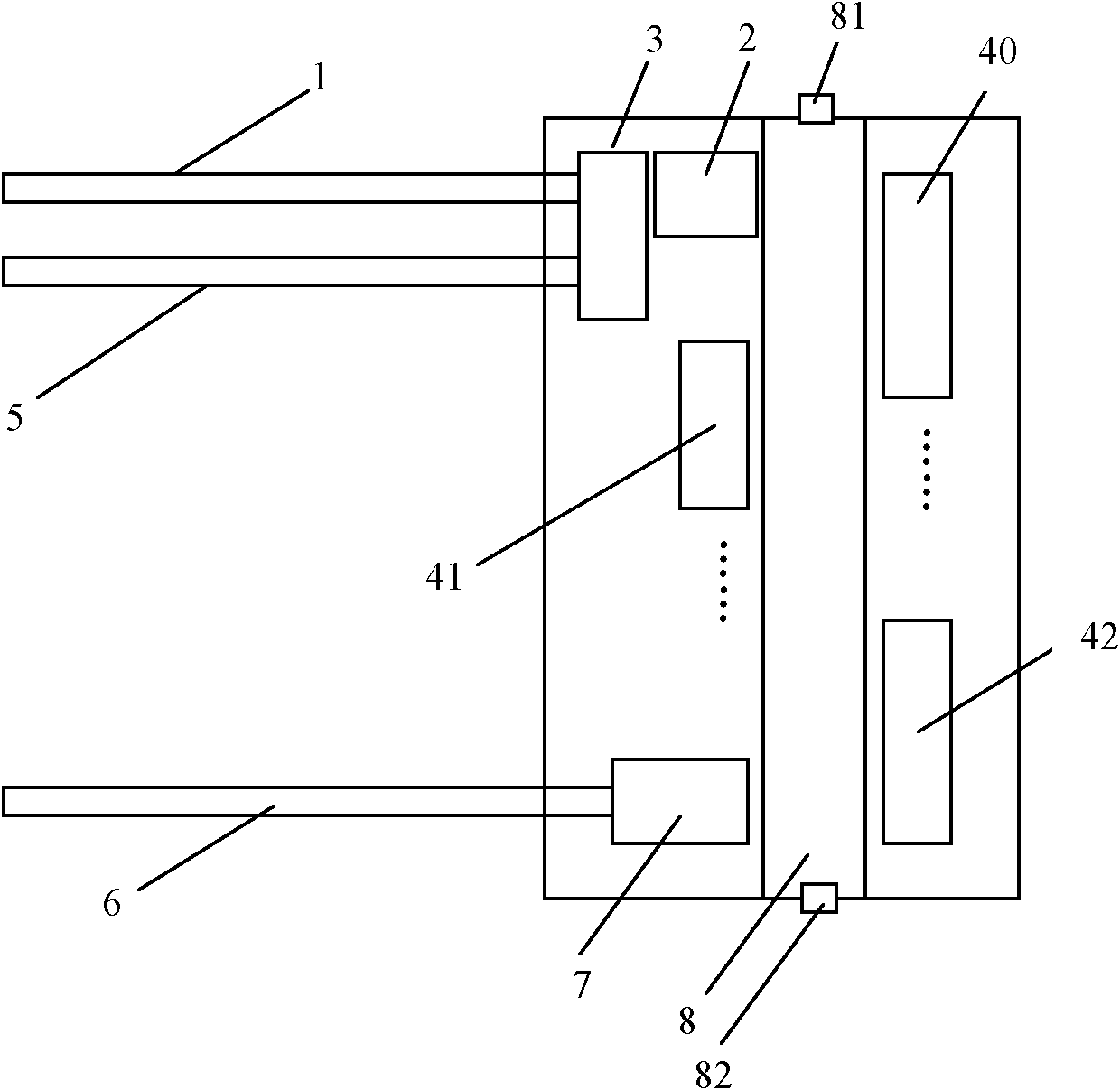
[0051] see figure 2 , similar to Embodiment 1, the difference is that the output end of the incident fiber 1 is connected to the fiber coupler 3 (light splitting component), and the incident light is divided into 2 paths by the fiber coupler 3 (light splitting component), and one of them enters as a reference light The reference light output port of the fiber coupler 3 enters the reference fiber 5, and the other one as information light enters the incident fiber collimator 2 through the information light output port of the fiber coupler 3, and is output after being collimated by the incident fiber collimator 2 The information light enters the sample chamber 8, passes through the sample multiple times after multiple reflections by the three conical reflective prisms 40, 41 and 42, and after being absorbed by the sample, the information light is coupled into the return optical fiber 6, and guided by the return optical fiber 6 to External instrument host. exist figure 2 Among...


PUM


Abstract

The invention discloses a detection head of a spectrophotometer, relating to the spectrophotometer. The detection head of the spectrophotometer has small volume and high sensitivity, can be separated with an instruement host and is played once plugged, is portable; and with the adoption of the detection head of the spectrophotometer, the interference of stray lights is reduced, the immediate detection requirements in field and site are satisfied, and the detection stability can be greatly enhanced. The detection head of the spectrophotometer comprises a shell, an incidence optical fiber, a reference optical fiber, an incidence optical fiber collimator, a light splitting part, an optical reflection part, a return optical fiber collimator, a return optical fiber and a sample chamber. Because an optical fiber type probe is adopted, the anti-interference performance is enhanced with optical fiber transmission. Because a conical reflecting prism is adopted, an integrated multi-optical-pathabsorption optical detection head which has compact structure can be obtained, and therefore, under the condition without increasing the length of a sample chamber, an absorption optical path is enlarged, the interference of stray lights is reduced, the sensitivity is enhanced, and the optical regulation difficulty is also lowered; while, spectrophotometers at home and aboard are all in a single absorption optical path optical detection head. Because a reference optical path is arranged, the detection stability can be greatly enhanced.

Description

technical field [0001] The invention relates to a spectrophotometer, in particular to a spectrophotometer detection head. Background technique [0002] As an optical analytical measuring instrument, a spectrophotometer is widely used in various fields. Since the existing spectrophotometer adopts sample mechanisms such as cuvettes and cuvettes, there are problems such as complicated operation, many interferences, large volume, low sensitivity, complex structure, and not easy to carry. With the development of science and technology, the demand for high-end spectrophotometers is increasing year by year, especially for field and on-site real-time detection, and the demand for high-precision analysis of samples is becoming more and more urgent. The plug-and-play detection head suitable for small instruments that eliminates stray light and improves the noise index is a development trend and the focus of research at home and abroad. [0003] Chinese patent 2008100706512 discloses...

Claims


Application Information

Patent Timeline
Patent Type & Authority Applications(China)
IPC IPC(8): G01J3/02
Inventor 陈延平黄元庆支远张建寰林振衡胡天林
Owner XIAMEN UNIV
Why Eureka
Try Eureka