Method to detect or monitor the demagnetization of a magnet

a demagnetization and magnet technology, applied in the direction of electrical generator control, machine/engine, susceptibility measurement, etc., can solve the problems of respective change in the magnetic flux of the generator, irreversible and just partly recoverable loss, etc., to achieve easy and cost-effective

Active Publication Date: 2017-02-02
SIEMENS GAMESA RENEWABLE ENERGY AS
View PDF4 Cites 16 Cited by
  • Summary
  • Abstract
  • Description
  • Claims
  • Application Information

AI Technical Summary

Benefits of technology

[0011]An aspect relates to providing a method to detect the demagnetization of the wind turbine magnets in an easy and cost effective way.

Problems solved by technology

Permanent magnet generators are widely used in wind turbines due to its high efficiency and low weight.
An irreversible and just partly recoverable loss occurs when the magnetic output falls with rising temperatures but does not fully return when the magnet cools down.
Therefore, a change of the current remanent flux density of the permanent magnets, e.g. due to temperature, or ageing, will result in a respective change in the generator's magnetic flux.
An irreversible and just partly recoverable loss occurs when the magnetic output falls with rising temperatures but does not fully return when the magnet cools down.
Due to a harsh environment operating conditions of a wind turbine, the generator's permanent magnets can lose their magnetism, i.e. can be demagnetized, due to different reasons.
Demagnetization can be caused by a high magnet temperature or by high short circuit currents occurring in the stator windings of a permanent magnet generator in case of generator or electronic converter failure.

Method used


Image

  • Method to detect or monitor the demagnetization of a magnet
  • Method to detect or monitor the demagnetization of a magnet
  • Method to detect or monitor the demagnetization of a magnet

Examples


Embodiment Construction

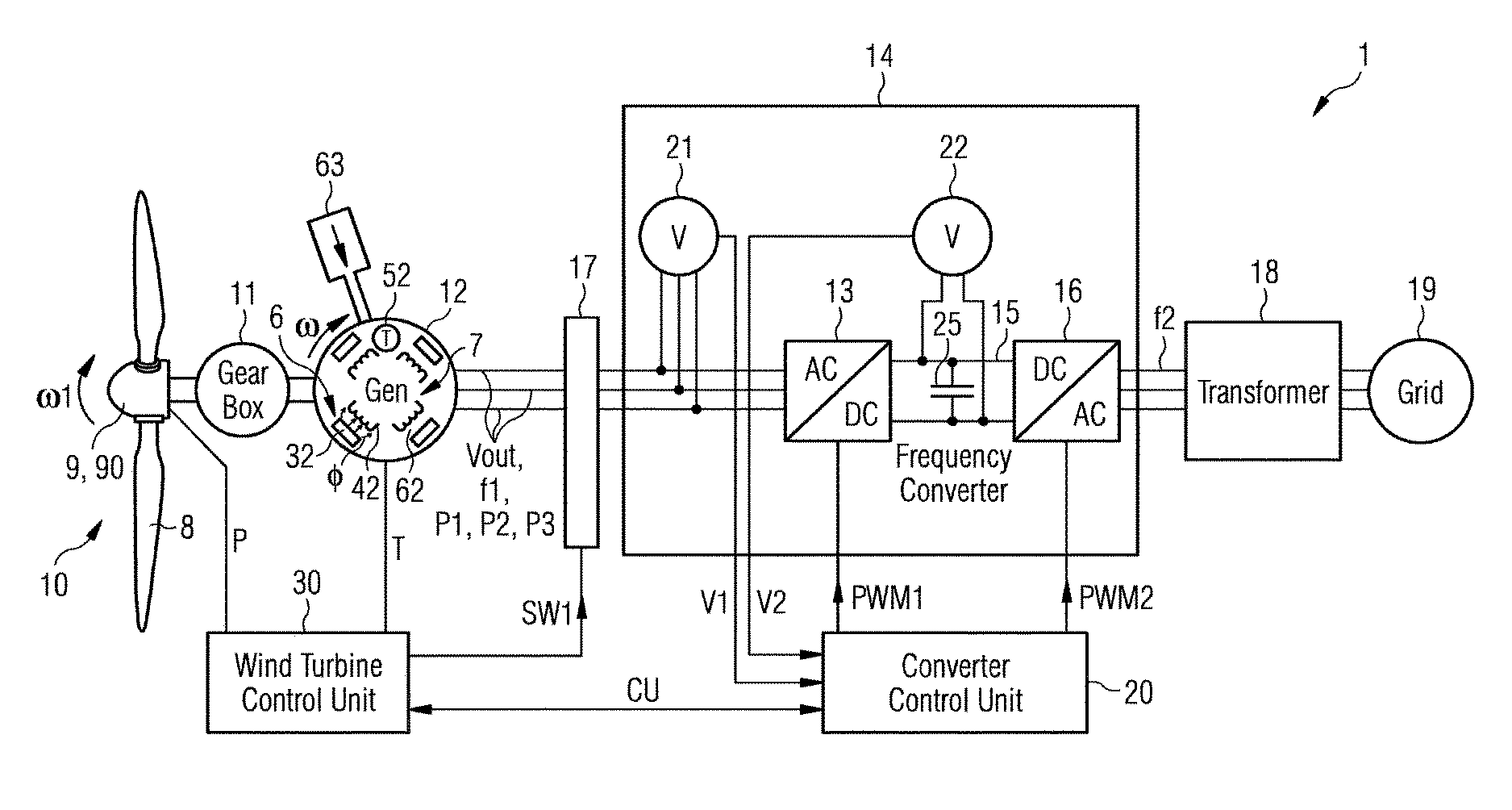
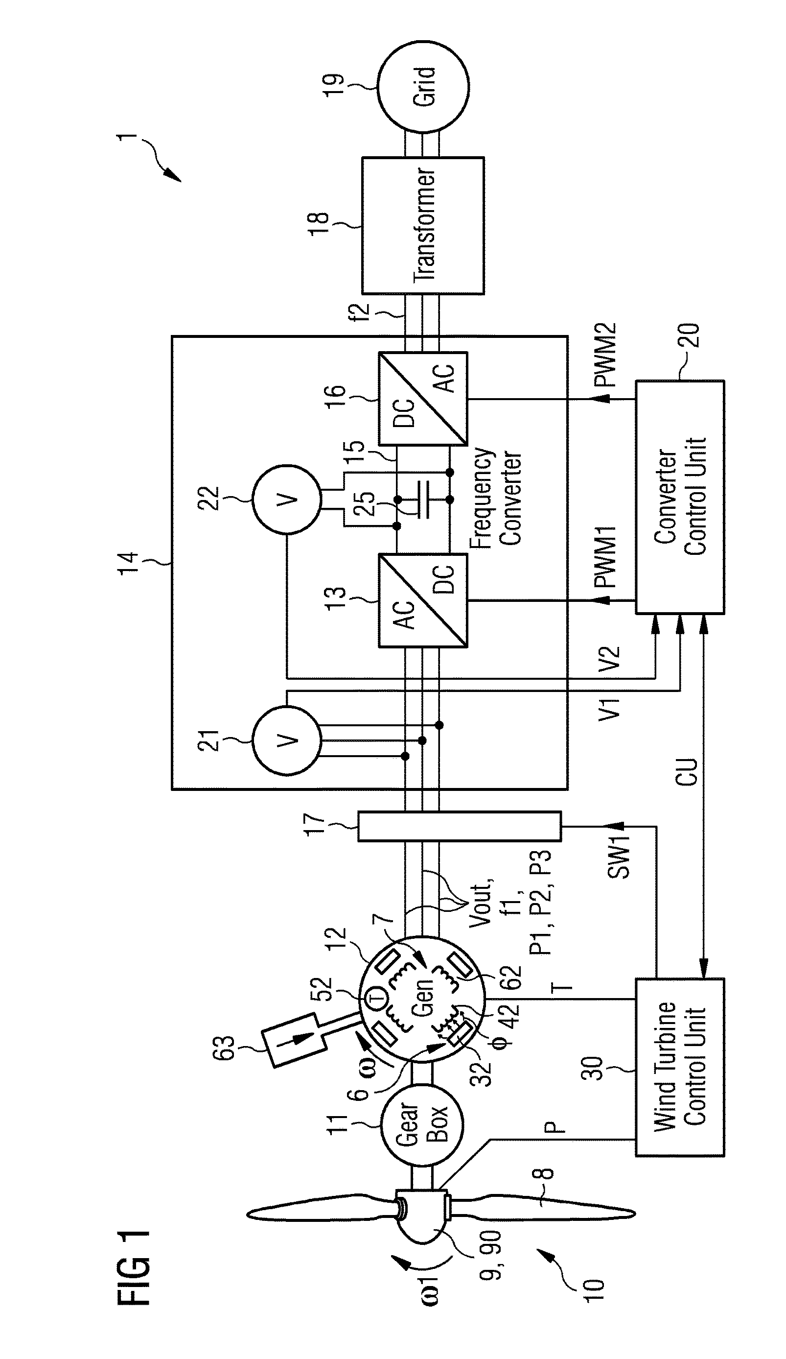
[0070]FIG. 1 shows a geared variable speed wind turbine 1. The wind turbine 1 comprises a wind turbine rotor 10 which in operation of the wind turbine 1 is driven by wind. The wind turbine rotor 10 comprises a hub 9 with three blades 8. The hub 9 comprises a pitch control system 90 to control the angle of the blades 8 in order to control the rotational speed ω1 of the wind turbine rotor 10. The wind turbine 1 further comprises an electric generator 12 being driven by the wind turbine rotor 10. In between the wind turbine rotor 10 and the electric generator 12 there is provided a gear box 11. However, it is mentioned that this gear box 11 is an optional component which depending on the specific type of wind turbine 1 may not be necessary, e.g. in case of a direct drive wind turbine. The electric generator 12 is a permanent magnet generator 12. A permanent magnet generator is a generator where the excitation magnetic field is provided by permanent magnets instead by the current flowin...


PUM


Abstract

A method to detect a decrease of the demagnetization of permanent magnets of the generator of a wind turbine, wherein a frequency converter is able to adapt to the variable frequency of the generator output voltage to the frequency of a power grid, wherein the AC / DC converter or the DC / AC converter of the frequency converter is been disabled, the electrical connections between the generator and the frequency converter are switched on via circuit breakers, the generator speed is determined; the generator output voltage is determined by a voltage sensor which is part of the frequency converter,the magnetic flux density of the generator is calculated depending on the generator speed and the generator output voltage, a demagnetization event is determined by comparing the resulting flux density value with a predetermined flux density value is provided.

Description

CROSS-REFERENCE TO RELATED APPLICATIONS[0001]This application claims priority to European application No. EP 15178453.5 having a filing date of Jul. 27, 2015, the entire contents of which are hereby incorporated by reference.FIELD OF TECHNOLOGY[0002]The following relates to a method to detect or monitor the demagnetization of the permanent magnets of the generator of a wind turbine and a respective wind turbine.BACKGROUND[0003]A modern direct drive wind turbine comprises a permanent magnet generator (PMG) in which the excitation field is provided by permanent magnets instead of a coil. Permanent magnet generators are widely used in wind turbines due to its high efficiency and low weight.[0004]The document “WP131001EN-Generator circuit breakers have special requirements for generator protection” shows an example of circuit breakers which can be used in wind turbine generators.[0005]Document EP 2 605 390 A1 shows a frequency converter which is able to convert the frequency of the outp...

Claims


Application Information

Patent Timeline
Patent Type & Authority Applications(United States)
IPC IPC(8): G01R33/16F03D9/00F03D17/00
CPCG01R33/16F03D9/003F03D17/00G01R33/12H02M5/458H02P9/48F03D9/255Y02E10/76Y02E10/72
Inventor DENG, HENG
Owner SIEMENS GAMESA RENEWABLE ENERGY AS
Why Eureka
Try Eureka