Power storage device, battery management unit, and electronic device

a technology of power storage device and battery management unit, which is applied in the direction of secondary cell servicing/maintenance, cell components, jackets/cases materials, etc., can solve the problems reducing the discharge capacity in some cases, and entering impurities into the power storage device. , to achieve the effect of reducing the characteristics of the power storage device and reducing the discharge capacity

Active Publication Date: 2017-02-02
SEMICON ENERGY LAB CO LTD
View PDF3 Cites 28 Cited by
  • Summary
  • Abstract
  • Description
  • Claims
  • Application Information

AI Technical Summary

Benefits of technology

[0007]Entry of impurities into a power storage device reduces the characteristics of the power storage device. For example, impurities such as water entering a nonaqueous electrolytic solution reduces discharge capacity in some cases. Poor airtightness of an exterior body of a power storage device, for example, might allow components in the air to go into the exterior body, which might result in entry of impurities into the power storage device.

Problems solved by technology

Entry of impurities into a power storage device reduces the characteristics of the power storage device.
For example, impurities such as water entering a nonaqueous electrolytic solution reduces discharge capacity in some cases.
Poor airtightness of an exterior body of a power storage device, for example, might allow components in the air to go into the exterior body, which might result in entry of impurities into the power storage device.
Power storage devices incorporated in electronic devices used while being worn on human bodies might be repeatedly bent at the moment of repeatedly attaching and detaching the electronic devices.
The repeated bending of the power storage devices causes deterioration of their exterior bodies, possibly allowing entry of impurities such as moisture into the exterior body.

Method used


Image

  • Power storage device, battery management unit, and electronic device
  • Power storage device, battery management unit, and electronic device
  • Power storage device, battery management unit, and electronic device

Examples


embodiment 1

[0081]In this embodiment, power storage devices of embodiments of the present invention and exterior bodies of the power storage devices are described.

[0082]Examples of the power storage device include secondary batteries utilizing electrochemical reaction (e.g., lithium-ion batteries), electrochemical capacitors (e.g., electric double layer capacitors and redox capacitors), air cells, and fuel cells.

[0083]It is preferable that a power storage device of one embodiment of the present invention can be repeatedly charged and discharged.

[0084]In charging and discharging of a power storage device, an electrolytic solution might be decomposed at the reaction potential of an electrode. Decomposition reactions of an electrolytic solution are irreversible in many cases and thus sometimes reduce the charge and discharge efficiency of the power storage device. When the charge and discharge efficiency is reduced, the power storage device suffers reduction in discharge capacity.

[0085]In addition...

embodiment 2

[0192]In this embodiment, power storage devices of embodiments of the present invention are described.

[0193]An example of a power storage device including the exterior body of one embodiment of the present invention is described below.

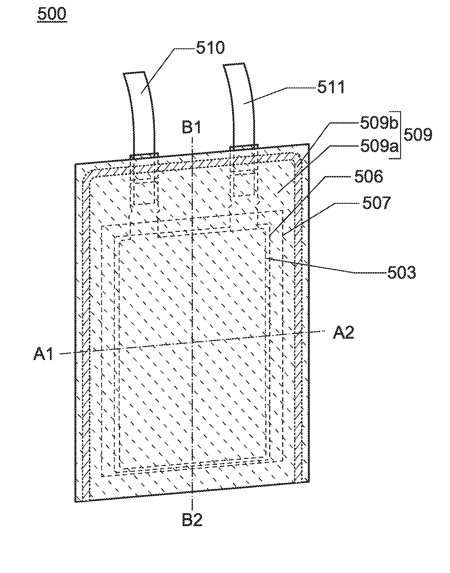
[0194]FIG. 10 illustrates a thin storage battery as an example of a power storage device. When a flexible thin storage battery is used in an electronic device at least part of which is flexible, the storage battery can be bent as the electronic device changes their shapes.

[0195]FIG. 10 is an external view of a power storage device 500, which is a thin storage battery. FIG. 11A is a cross-sectional view along dashed-dotted line A1-A2 in FIG. 10, and FIG. 11B is a cross-sectional view along dashed-dotted line B1-B2 in FIG. 10. The power storage device 500 includes a positive electrode 503 including a positive electrode current collector 501 and a positive electrode active material layer 502, a negative electrode 506 including a negative electrode current...

embodiment 3

[0295]In this embodiment, a positive electrode and a negative electrode of a power storage device of one embodiment of the present invention are described.

[0296]The positive electrode of one embodiment of the present invention preferably includes a positive electrode active material. The positive electrode of one embodiment of the present invention may include a binder. The positive electrode of one embodiment of the present invention may include a conductive additive.

[0297]The negative electrode of one embodiment of the present invention preferably includes a negative electrode active material. The negative electrode of one embodiment of the present invention may include a binder. The negative electrode of one embodiment of the present invention may include a conductive additive.

[0298]As a negative electrode active material, for example, a carbon-based material, an alloy-based material, or the like can be used.

[0299]As the carbon-based material, graphite, graphitizing carbon (soft ...


PUM

PropertyMeasurementUnit
heightaaaaaaaaaa
heightaaaaaaaaaa
thicknessaaaaaaaaaa

Abstract

A repeatedly bendable power storage device. A highly reliable power storage device. A long-life power storage device. A repeatedly bendable electronic device. A flexible electronic device. The power storage device includes a film, a positive electrode, and a negative electrode. The film includes a plurality of projections. A difference between the maximum height and the minimum height of a surface of the film is greater than or equal to 0.15 mm and less than 0.8 mm. The modulus of rigidity of the film is less than 6.5×10⁹ N. The film includes a metal layer. The thickness of the metal layer is greater than or equal to 5 μm and less than or equal to 200 μm. The positive electrode and the negative electrode are surrounded by the film.

Description

BACKGROUND OF THE INVENTION[0001]1. Field of the Invention[0002]The present invention relates to an object, a method, or a manufacturing method. The present invention relates to a process, a machine, manufacture, or a composition of matter. In particular, one embodiment of the present invention relates to a semiconductor device, a display device, a light-emitting device, a power storage device, a memory device, a driving method thereof, a manufacturing method thereof, or an evaluation method thereof. In particular, one embodiment of the present invention relates to a power storage device, a manufacturing method thereof, and an evaluation method thereof.[0003]Note that a power storage device in this specification refers to every element and / or device having a function of storing electric power.[0004]2. Description of the Related Art[0005]In recent years, a variety of power storage devices, for example, secondary batteries such as lithium-ion secondary batteries, lithium-ion capacitor...

Claims


Application Information

Patent Timeline
Patent Type & Authority Applications(United States)
IPC IPC(8): H01M2/02H01G11/56H01G11/20H01G11/06H01M10/42H01M10/0525H01M50/119H01M50/133
CPCH01M2/0275H01M10/425H01M10/0525H01M2010/4271H01G11/06H01G11/56H01G11/20H01G11/78H01G11/80H01G11/82Y02T10/70H01M50/133H01M50/119Y02E60/10Y02E60/13
Inventor GOTO, JUNYANAKAGAWA, AISATO, YUIKA
Owner SEMICON ENERGY LAB CO LTD
Why Eureka
Try Eureka